
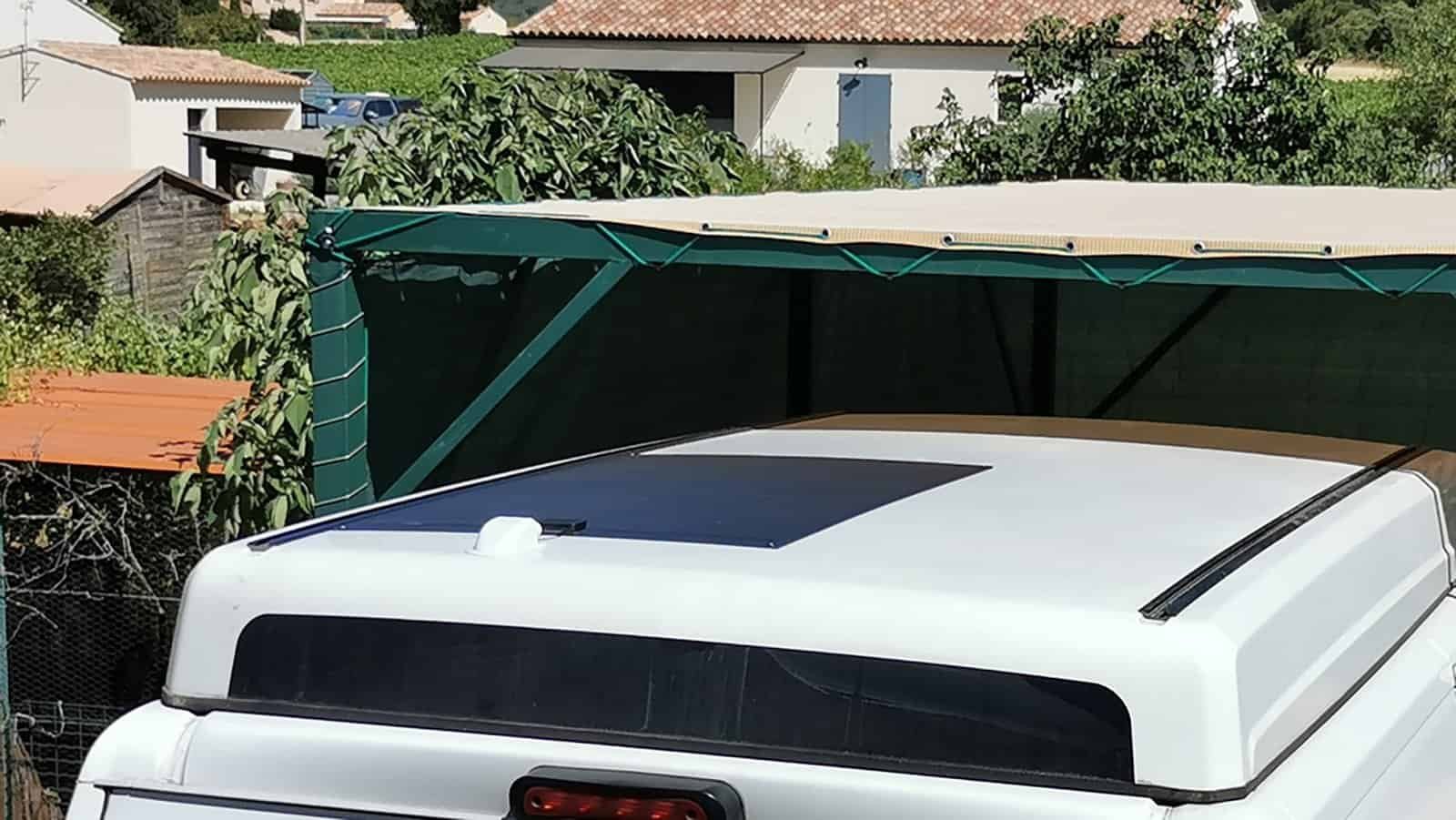
Short answer: measure the usable area, not the total area, then multiply it by a real whole-module power density. Today’s flexible crystalline-silicon laminates run roughly 170–205 watts per square metre of laminate. Thin-film and organic films run lower. And on a typical vehicle or boat roof, only 55–70% of the total surface survives once you subtract edges, vents, hatches and hardware. That gap between “total” and “usable” decides your wattage far more than the curve ever will.
Anyone who builds RVs, boats, vans, portable power products or outdoor equipment has asked a supplier the same question. My roof is this big and it curves. How many watts can I fit?
The answer usually comes back wrong. Length times width, multiplied by whatever efficiency figure sits on a datasheet, and there’s your number. It is almost always too high.
What follows is how to work it out properly — the arithmetic engineers actually use, with every assumption written down so you can argue with it.
1. Start With the Usable Area, Not the Total Area
Total area is the number on your drawing. Usable area is what survives contact with reality.
Every roof loses space to things that have nothing to do with solar:
- Edge clearance. Nobody laminates up to a gutter, drip rail or weld seam. Most builders keep 50–150 mm clear all round.
- Roof vents and hatches. A 400 × 400 mm vent needs service clearance around it, so it doesn’t cost you 0.16 m². It costs closer to 0.36 m².
- Air conditioners and fridge vents. Big footprints, and they throw shadows.
- Antennas, satellite domes, aerials and lights. Small footprint, generous keep-out.
- Mounting hardware and rails. Bolt lines, roof rack feet, awning brackets.
- Walkways and access paths. On boats and larger vehicles, somebody has to reach that hatch.
- Curvature transitions. Where a flat crown rolls into a tight corner radius, a laminate cannot follow. That strip is dead.
Take a 5,000 × 2,000 mm van roof and walk it through:
| Step | Area |
|---|---|
| Total roof | 10.00 m² |
| After 100 mm perimeter clearance | 8.64 m² |
| Minus two vents with clearance (0.36 m² each) | 7.92 m² |
| Minus air conditioner with clearance (1.3 × 0.9 m) | 6.75 m² |
| Minus antenna base with clearance (0.5 × 0.5 m) | 6.50 m² |
Ten square metres in. Six and a half out. That’s 65%.
Run both numbers at 202 W/m² and the difference is stark: the total-area answer says 2,020 W, the usable-area answer says 1,313 W. Same roof, 707 W apart, and only the second figure is honest.
That ratio lines up with what the wider industry reports. European work on vehicle-integrated solar puts a passenger car at 1.5–4.5 m² of solar surface and a van or bus at up to 10 m², with real systems delivering 150–600 Wp from it. Our 10 m² roof landing near 1,200 W sits at the top of that range — which is exactly where a well-designed custom layout should sit.
One complication remains. Those 6.50 m² are not one tidy rectangle; they are three or four odd-shaped zones. Filling them is a question of panel geometry, which is the next problem.
2. The Curve Itself Barely Adds Area — But It Can Cost You Yield
Almost nobody tells buyers this. A curved roof does give you more surface than its flat footprint. Just not much.
Bend a 2,000 mm roof into a gentle crown with a 60 mm rise and the arc across it measures 2,004.8 mm. That’s 0.24% more area. Not five percent. Not ten. A quarter of one percent.
Push harder and it improves, but modestly. A boat cabin top of the same width with a 300 mm rise gives an arc of 2,118 mm — 5.9% more area.
So the curve isn’t a bonus. It’s a constraint.
What curvature actually costs you in energy
The best public measurement comes from IEA-PVPS Task 17. Researchers instrumented a real vehicle roof measuring 158 × 106 cm with a 5 × 5 matrix of half-cut M6 cells and thermocouples, then logged it every minute for eight days in August at Le Bourget du Lac, France.
Their clear-sky results are worth reading twice. Irradiance between the best- and worst-oriented cell on the same roof differed by up to 250 W/m² — a 21% spread. Cell temperature varied by as much as 13 °C. On rainy days, both effects all but disappeared: under 20 W/m² and under 3 °C, because diffuse light reaches every part of the surface equally.
Converting that into energy, and assuming a 3 m radius of curvature with every cell wired in one series string, the roof gives up 12–17% on a clear sunny day and roughly 6% on a rainy one against a flat surface.
That hypothesis carries the whole design lesson, so read it carefully. The 12–17% is not a measured module output. It is what happens when one series string spans an entire curve and the worst-lit cell throttles every other cell in the chain. Worst case, in other words — and avoidable. The same report benchmarks against the conventional planning figure of 8–10% energy loss per year versus an equivalent flat horizontal panel. Budget with 8–10% annually; treat 12–17% as what a badly zoned array surrenders on the best days of the year.
Why it happens, and what to do about it
Two mechanisms are at work, and they compound.
Cosine loss. Every patch of a curved surface points somewhere different. At any given moment only part of the roof faces the sun well; the rest catches light at an angle.
Electrical mismatch. Cells in series all carry the same current, and the weakest one sets the ceiling. When one flank of a curve is bright and the other is dim, the bright cells simply cannot deliver what they are capable of.
The remedy follows directly from the mechanism. Split the roof into electrical zones that share a similar orientation, and give each zone its own MPPT channel. The IEA-PVPS team recommends precisely this, while noting that it costs more. Ask your supplier to align substrings with orientation zones before they draw the layout, not after.
A word of caution on the numbers themselves. They come from one geometry, one location and eight days of one summer month, at a fairly aggressive 3 m radius. The researchers called for a full year of data. A gentle RV crown at an 8 m radius will lose considerably less.
The practical takeaway stays blunt: curving your array gains under 6% in area and can cost several times that in energy. Curve because your product requires it, not because you expect free watts.
3. Why Wattage Depends on Panel Geometry
Two panels of identical area can hold very different amounts of power. Most buyers find this genuinely surprising.
Compare two outlines, both exactly 0.60 m²: Panel A at 1,000 × 600 mm, and Panel B at 1,200 × 500 mm. Fill each with standard 182 mm (M10) cells, allowing a 15 mm border and 2 mm between cells. Those are typical values rather than universal ones, so check them against your own supplier’s layout rules.
Panel A takes 5 cells along its length and 3 across its width — 15 cells.
Panel B takes 6 along its length, but the 500 mm width defeats it. Three cells would need 550 mm and only 470 mm of usable width exists, so two is the limit. That’s 12 cells.
Same area. Twenty-five percent fewer cells.
| Outline (both 0.60 m²) | Full cells | At 24% cells | At 26% back-contact |
|---|---|---|---|
| 1,000 × 600 mm | 15 | ~107 W | ~116 W |
| 1,200 × 500 mm | 12 | ~86 W | ~93 W |
A 182 mm cell covers 0.0331 m². At a mainstream n-type efficiency near 24% that works out to about 8.0 W per cell; at the roughly 26% our back-contact cells reach, about 8.6 W. Both columns assume a typical 90% cell-to-module ratio.
Now look at what doesn’t move. Better cells lift both panels by the same proportion, and the 25% gap between the two outlines stays exactly where it was. Cell technology shifts your baseline. Geometry shifts your result.
Hence the rule worth memorising: an outline that wastes a strip narrower than one cell wastes that strip completely. A 500 mm width with 182 mm cells leaves 104 mm of dead space, and there is no partial credit available.
A caveat on the arithmetic: silicon cells are pseudo-square, with chamfered corners left over from the round ingot, so tiling them as perfect rectangles slightly overstates active area. Cell count is unaffected, and that is what this comparison turns on.
4. Cell Size Changes What You Can Fit
Keep Panel B exactly as it is and change one thing: use half-cut cells instead of full ones.
A 182 mm cell cut in half becomes 182 × 91 mm. That awkward 470 mm width now holds five half-cells where it held two full ones.
| Outline | Full 182 mm cells | Half-cut 182 × 91 mm | Power at 24% cells |
|---|---|---|---|
| 1,000 × 600 mm | 15 cells | 30 half-cells | ~107 W either way |
| 1,200 × 500 mm | 12 cells | 30 half-cells | 86 W → ~107 W |
Twenty-five percent more power out of Panel B. The area didn’t change. The cell efficiency didn’t change. Only the cell format did.
This is the single most useful idea on the page. Cell geometry is a design lever, and hardly any buyer ever reaches for it.
The five variables worth negotiating
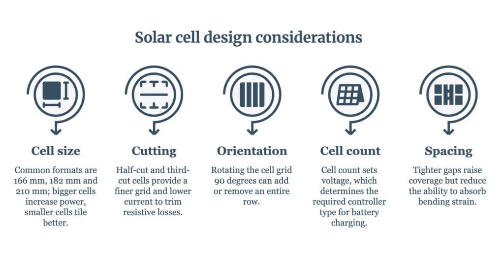
Cell size. Common formats are 166 mm, 182 mm and 210 mm. Bigger cells mean more power per cell and fewer interconnections; smaller cells tile awkward outlines better.
Cutting. Half-cut and third-cut cells hand you a finer grid to work with, and they lower current per string, which trims resistive losses. Our CLM-130MF uses 33 half-cut cells in a 3 × 11 array to reach 130 W inside a 1,090 × 590 mm outline.
Orientation. Rotating the cell grid 90 degrees can add or remove an entire row. Always ask your manufacturer to run both.
Cell count and string layout. Cell count sets voltage. Thirty-three half-cut cells in series give about 20 V at maximum power, which calls for an MPPT controller on a 12 V bank — a PWM controller would clamp the array down to battery voltage and surrender somewhere around 35–40% of the harvest. Change the count and you change the voltage, so the best-fitting layout sometimes produces an inconvenient one. That trade is real and has to be made deliberately.
Spacing. Tighter cell gaps raise coverage, but those gaps also absorb bending strain. On a curved installation, squeezing them to gain a single percent of coverage can shorten interconnect life. Engineering trade, not free win.
For reference, the CLM-130MF covers about 85% of its outline with active cells — a healthy figure for a flexible laminate. Should a supplier quote coverage above 92%, ask how they handle edge sealing and bend strain.
5. Minimum Bend Radius Decides What Is Even Possible
Before calculating anything, confirm that a laminate can physically sit on your surface.
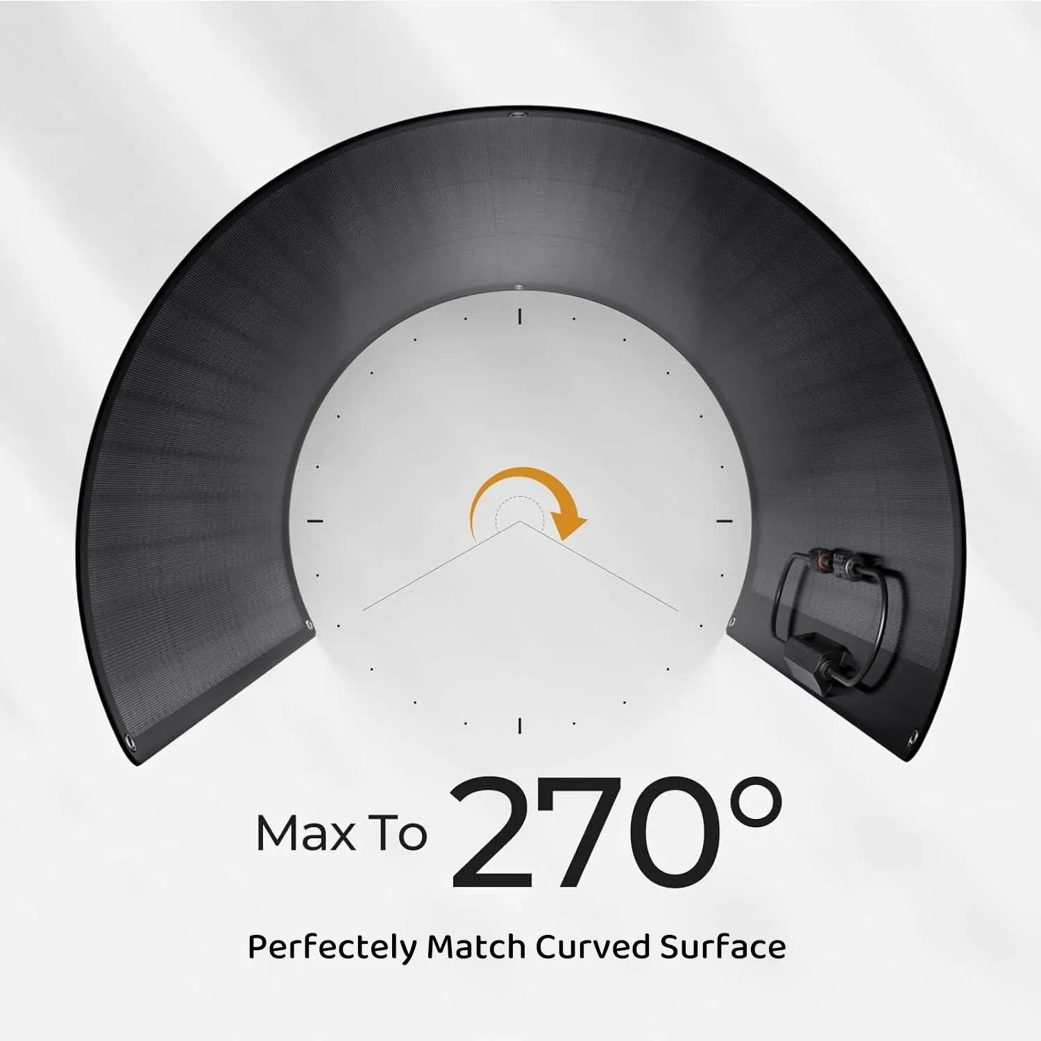
Which brings us to a specific piece of nonsense. Listings routinely advertise panels as “bendable to 180°”, “240° flexible” or “flexes up to 30 degrees”. An angle is not a mechanical specification. Thirty degrees across a 300 mm panel is brutal. The same thirty degrees across a 2,000 mm panel is gentle. Without the length, the angle tells you nothing at all.
The real specification is minimum bend radius, and published values vary enormously:
| Product type | Published minimum radius |
|---|---|
| Flexible ETFE back-contact (Couleenergy CLM-130MF) | ~300 mm |
| Organic PV film (Heliatek HeliaSol) | 500 mm, one axis only |
| CIGS thin-film roofing laminate (MiaSolé FLEX) | 508 mm |
| Marine semi-flexible (European brand) | 1,000 mm |
| Reinforced semi-flexible series | 3,000 mm |
The last two figures come from published installation manuals. We haven’t named those brands because they compete with us directly, and we would rather you checked their manuals yourself than took our word for it.
Ten to one, top to bottom. “Flexible” means almost nothing on its own.
One datasheet, two different numbers
It gets worse than vague marketing, and here is a documented case rather than an abstract warning. Heliatek’s HeliaSol 436-2000-AFA datasheet, revision 09, specifies a minimum bending radius of 50 cm for unidirectional curved surfaces in its mechanical table. The product label reproduced on the same datasheet, in the technical drawing two panels earlier, reads “Minimum bending radius: 20cm”.
Same document. Same revision. A factor of 2.5 apart. We’re not singling Heliatek out, either — this happens across the industry, and their datasheet is simply one of the few detailed enough to catch it in.
The defence is procedural, not technical. Put the number in your purchase order. Quote the datasheet revision and date you designed against, name the figure, and get it confirmed in writing. A number printed on a label is not a contractual specification.
Measuring your own surface
A tape measure is enough. Measure the chord c across the curve and the sag s at its midpoint. For a circular arc the relationship is exact, not an approximation:
R = c² ÷ (8 × s) + s ÷ 2
Working the other way, if you already know the radius, here is the rise a 1,000 mm panel would need to follow:
| Bend radius | Rise across a 1,000 mm panel |
|---|---|
| 300 mm | 329 mm |
| 500 mm | 230 mm |
| 1,000 mm | 122 mm |
| 2,000 mm | 62 mm |
| 3,000 mm | 42 mm |
| 5,000 mm | 25 mm |
One detail trips people up here. That 1,000 mm is measured along the panel, not across the gap it spans — manufacturers specify it that way because panel length is what you know. Measure the straight-line chord instead and the same radius gives a different rise: 134 mm rather than 122 mm at R = 1 m. A small discrepancy, and exactly the kind that turns into a cracked cell.
Two questions before you commit
One axis or two? A cylinder is developable, so a flat sheet wraps around it without stretching. A dome, a saddle or a vehicle corner curves in two directions at once, and a large flat laminate cannot follow that — it will bridge, wrinkle or crack cells. Heliatek’s mounting specification is unambiguous on the point: flat, or bent in one axis only. Compound curves need smaller tiles, narrow strips or a segmented layout with gaps.
Once or repeatedly? A panel formed once and bonded permanently is a static bend. A panel on a fabric canopy or a folding product flexes over and over. Those are entirely different qualifications, and a defined test now separates them — see section 8.
6. Why Custom Panels Can Produce More Power Without Increasing Area
Back to the van roof, where 6.50 m² of usable area breaks into three zones:
- Zone A: 1,800 × 1,800 mm
- Zone B: 1,500 × 1,800 mm
- Zone C: 900 × 640 mm
Try filling it with standard 1,090 × 590 mm panels. Zone A takes four. Zone B takes three. Zone C takes none at all, because a 1,090 mm panel will not go into a 900 mm space.
Seven panels × 130 W = 910 W. Your laminate covers 4.50 m² of the 6.50 m² available — 69% zone fill, and only 45% of the roof you started with.
Build the panels to the zones instead and everything else stays constant. Same cells, same efficiency, same technology. Only the outlines change, plus a small panel for Zone C. Custom outlines realistically reach 85–95% zone fill; at 90% you laminate 5.87 m² and reach roughly 1,185 W.
| Approach | Laminate area | Output |
|---|---|---|
| Standard catalogue sizes | 4.50 m² | 910 W |
| Custom outlines | 5.87 m² | ~1,185 W |
| Gain | +1.37 m² | +275 W (+30%) |
Thirty percent more power, and not one more efficient cell was purchased.
Which is why we keep telling engineers that on a constrained surface, format outranks cell technology. Upgrading from a good cell to a class-leading one might buy 4 or 5%. Moving from a catalogue outline to a fitted one buys 20–30%. It isn’t close.
Space utilisation, not efficiency, is what fills your roof.
This is our normal job, not a special project.
Couleenergy builds flexible ETFE back-contact modules and semi-rigid panels to customer outlines — custom cell layouts, custom voltages, custom junction box positions, custom cable exits. Low MOQ, because most OEM programmes begin with a pilot rather than a container. Send us your dimensions →
7. A Simple Method to Estimate Your Maximum PV Output
The whole calculation takes two minutes.
Estimated Wp = Usable area (m²) × Coverage factor × Module density (W/m²)
Step 1 — Measure the usable skin
Follow the curve, not the footprint. Break the surface into zones, subtract every keep-out, and use the chord-and-sag formula for curved sections.
Step 2 — Pick a coverage factor
This is how much of your usable zone actually becomes laminate.
| Scenario | Coverage | When to use it |
|---|---|---|
| Conservative | 60–70% | Early concept, standard rectangular panels, unknown keep-outs |
| Design target | 75–85% | CAD layout with semi-custom sizes |
| Optimised custom | 85–95% | Tailored outlines and electrical design |
Treat these as planning assumptions rather than industry constants. Your real figure emerges from a nesting drawing.
Step 3 — Pick a whole-module power density
Rated power divided by outside dimensions, taken from a dated datasheet. Nothing else.
| Technology | Whole-module density | What you trade |
|---|---|---|
| Organic PV film | ~57–63 W/m² | Lowest density by a wide margin. In exchange: under 2 kg/m², and a temperature coefficient of 0.00%/°C from 25 to 65 °C, so it does not fade on a hot bonded roof. Power tolerance runs ±10%, far looser than silicon. |
| CIGS thin-film laminate | ~120–160 W/m² | Continuous construction at roughly 2 kg/m², available in very long narrow formats that suit constrained strips well. |
| Glass-free mono-PERC silicon | ~170–180 W/m² | Mature and widely stocked, but a generation behind on both density and temperature behaviour. |
| Current n-type / back-contact silicon | ~190–205 W/m² | Highest density, best temperature coefficients, tight positive-only tolerances. Premium pricing. |
Densities are calculated from each manufacturer’s published nameplate power divided by published external dimensions. Product lines and availability change, so confirm both at RFQ stage.
Our CLM-130MF sits at the top of that last band: 130 W in a 1,090 × 590 mm outline works out to 202 W/m², or 20.2% whole-module efficiency.
The efficiency trap that costs buyers a fifth of their roof
Never size an area using cell efficiency, aperture efficiency, or anything except whole-module density. MiaSolé’s own customer FAQ draws the distinction cleanly: module area counts both the active and inactive surface of the product, while aperture efficiency looks only at the active part. Now watch what that does to real numbers.
- Heliatek publishes 7.2–8.0% aperture efficiency for HeliaSol. Divide its 50–55 W by the actual 2,000 × 436 mm footprint and you land at 5.7–6.3%. About a fifth of the figure disappears.
- MiaSolé advertises aperture efficiency as high as 17.5% for the FLEX-03W. Divide 490–540 W by its 2,583 × 1,292 mm footprint and you land at 14.7–16.2%.
- A 26% back-contact cell, once it sits in a laminate at 85% coverage with normal module losses, becomes roughly a 20% module.
Depending on technology, that gap swallows somewhere between 8% and 22% of the answer. Size a roof against the wrong figure and your project comes up short by exactly that much.
Step 4 — Do the sum
For 6.50 m² of usable area, at 90% coverage, with 202 W/m² modules:
6.50 × 0.90 × 202 ≈ 1,180 Wp
Wp is not Wh, and the gap is wider than most buyers expect
What you now have is STC nameplate power — measured in a laboratory at 1,000 W/m² and 25 °C cell temperature. It is not what your product delivers on a Tuesday in October.
Several things pull real daily energy below it:
- Heat. A bonded panel has no air behind it. Back-contact cells lose about 0.26% of rated power per degree above 25 °C, so a roof at 65 °C costs around 10%. The IEA-PVPS test roof reached 60 °C on clear summer days.
- Curvature mismatch. Budget 8–10% annually, and more if the array is one long series string.
- Orientation. A horizontal roof is not tilted toward the sun.
- Shading. Trees, buildings, masts, other vehicles.
- Soiling. Dust, salt and bird droppings, particularly on low-tilt surfaces that rain washes poorly.
As a sanity check, European industry data puts today’s vehicle-integrated systems at 150–600 Wp depending on available surface, generating an average of 0.5 to 2.5 kWh per day under European conditions. Any energy model implying far more than that from a vehicle roof has an optimistic assumption hiding in it somewhere.
Treat Wp as a specification and Wh/day as a separate question. A supplier who blurs the two is either careless or selling.
8. What the Standards Actually Cover — and Where They Stop
Short section, but skipping it is how OEM programmes get surprised late.
A bending test now exists. The 2021 edition of IEC 61215 added test methods for flexible modules, MQT 22 among them. The module is wound over a drum through repeated flex cycles while a small current monitors electrical continuity, so a cracked interconnect is caught at the cycle it occurs rather than at a final pass or fail. If your product flexes repeatedly instead of being formed once, ask for MQT 22 results, not a bend-radius claim. That same edition introduced cyclic mechanical load (MQT 20) and PID detection (MQT 21), and removed the NMOT test from the series entirely.
IEC 61215 also has a scope limit that matters here. The standard states plainly that it does not apply to systems that are not long-term applications, such as flexible modules installed in awnings or tenting. A certificate is not a blanket permission slip for every mobile or temporary use.
Consumer and portable products have their own route. IEC TS 63163:2021 covers terrestrial modules for consumer applications with shorter outdoor operation than IEC 61215 assumes, sorting them into three exposure categories — mobile, portable and high-exposure. It explicitly treats mobile and attached applications as needing less mechanical durability than portable ones, which are more prone to damage. Note that it qualifies the PV portion only, not your electronics.
Qualification is not a lifetime prediction. IEC 61215-1-1 says exactly that in its own words: test results are not construed as a quantitative prediction of module lifetime.
Vehicle integration still runs ahead of the standards. IEC TC 82 has formed project team PT 600 for vehicle-integrated PV, developing technical reports on performance testing, outdoor validation and energy rating for curved modules, with European standards bodies working alongside it. Until that work lands, define vibration, impact, corrosion, fire and electrical-integration requirements in your contract rather than by pointing at a terrestrial certificate.
Whatever certificate you are shown, ask for the number, the issuing laboratory, the full test report and the certified bill of materials. A logo on a brochure says nothing about which model was tested.
9. Send These 5 Measurements to Your Manufacturer
A full engineering package isn’t necessary to get a real answer. Five things are enough.
1. Length. The developed length along the surface, following the curve — not the projected footprint.
2. Width. Same rule. If the surface curves across its width as well, say so and give both.
3. Curvature. Chord and sag, or the radius directly. State the axis too: does the surface bend along its length, across its width, or both? And tell us whether the bend is permanent or repeated.
4. Mounting area and keep-outs. A simple sketch beats a paragraph every time. Mark vents, hatches, antennas, rails, walkways and the edge clearance you need, and say how the panel attaches — adhesive, grommets, rivets or a bonded frame.
5. Target voltage and power. Charging 12 V, 24 V or 48 V? MPPT or PWM? What’s your target wattage, and is it a floor or a ceiling? Voltage drives cell count, cell count drives layout, and settling this early saves a redesign later.
What you get back
- A nesting layout drawing showing panel outlines on your surface
- The active-area calculation behind it
- An electrical string plan with substring and diode positions
- A realistic Wp figure, with the assumptions listed
- A straight answer on whether a standard panel would serve you better
Send us your five measurements.
We’ll come back with a layout drawing and an honest wattage. A 3D file makes it faster still — STEP, IGES and DXF all work. And if a standard panel fits your surface well, we’ll tell you that too.
Frequently Asked Questions
How many watts of solar can I fit per square metre of curved roof?
Plan on 170–205 W per square metre of installed laminate for current flexible crystalline silicon. You won’t laminate every square metre, though. After edges, keep-outs and layout losses, installed power per square metre of total roof usually lands between about 90 and 140 W/m² on a well-designed build, and can drop to 70 on a cluttered one. The van example above works out at 118 W/m² of total roof.
Does bending a solar panel reduce its rated power?
Forming within the specified radius shouldn’t change the datasheet rating. Installed geometry is what costs you, because curvature creates uneven light and electrical mismatch. One instrumented vehicle study calculated a 12–17% loss on clear sunny days at a 3 m radius with all cells in one series string, against a conventional annual planning figure of 8–10%.
What does “240 degree flexible” actually mean?
Commercially, very little. An angle is not a strain specification, since the same angle across a longer panel is a gentler bend. Ask instead for the minimum bend radius in millimetres, the permitted bending axis, and either a flex cycle count or MQT 22 test results.
Can one large flexible solar panel cover a dome?
Usually not. A dome curves in two directions and a flat laminate cannot follow that without stretching. Manufacturers of flexible films typically permit bending in one axis only. Compound curves need segmented layouts, narrow strips or smaller tiles.
Are half-cut cells always better than full cells?
Not always, but often on constrained outlines. Half-cut cells tile awkward widths better and lower string current. They also double the number of interconnections, so ask about interconnect design if the panel will flex.
Do I need custom solar panels, or will standard ones do?
If your surface is a clean rectangle larger than a standard panel, buy standard. If it’s irregular, tight, curved or broken up by hardware, custom outlines will typically recover 20–30% more power from the same area.
Is IEC 61215 enough for a curved vehicle module?
No. It covers terrestrial design qualification, states that its results are not a lifetime prediction, and explicitly excludes non-long-term applications such as awnings and tenting. Consumer and portable products have their own path in IEC TS 63163. Vehicle and marine integration needs duty-cycle requirements defined contractually, since international VIPV guidance remains in development at IEC TC 82.
What files do I need to send for a custom solar panel quote?
Five measurements will get you a first pass. For a production layout, send a 3D surface file, a 2D keep-out drawing, minimum radii per axis, target system voltage, and your expected shading and mounting conditions.
How This Article Was Checked
Every arithmetic example above was calculated rather than estimated, and can be reproduced from the dimensions given. Two assumption sets are stated openly because they change the answers: cell-fit examples use 182 mm cells with a 15 mm border and 2 mm gaps, and wattages assume a 24% cell with a 90% cell-to-module ratio unless a back-contact figure is named. All sources were opened and verified in September 2026.
Three points are deliberately left uncertain rather than smoothed over.
One. The coverage factors are planning ranges, not industry constants. Your real figure comes from a nesting drawing.
Two. The 12–17% curvature figure is a calculated worst case, not a measured module output. It assumes every cell sits in one series string on a 3 m radius, derived from eight days at a single French location in August 2023. The report’s own authors asked for a full year of data, and benchmark the conventional annual figure at 8–10%.
Three. Published power densities are calculated by us from each manufacturer’s stated power and dimensions. Product lines and availability change, and we have not independently tested any third-party product named here.
Published by Ningbo Coulee Tech Co., Ltd. (Couleenergy), a manufacturer of custom back-contact flexible, semi-rigid and rigid PV modules. Last reviewed September 2026.
Sources
- IEA-PVPS Task 17, Irradiance and Temperature Uniformity on Vehicle Roof (Report T17-05:2025) — primary source for every curvature figure used above, including the 8–10% annual benchmark.
- IEA-PVPS summary page for the same report
- pv magazine — New test method for curved VIPV surfaces
- TaiyangNews — IEA PVPS report highlights irradiance and temperature challenges in VIPV
- IEC 61215-1:2021 — adds the MQT 22 bending test for flexible modules; states the awnings and tenting scope exclusion; removes NMOT from the series.
- IEC 61215-1-1:2021 — test results are not construed as a quantitative prediction of module lifetime.
- IEC TS 63163:2021 — PV modules for consumer products; mobile, portable and high-exposure categories.
- pv magazine / IEC — IEC develops standards for vehicle-integrated photovoltaics (TC 82 PT 600)
- ETIP PV — Factsheet: Vehicle-Integrated Photovoltaics (November 2025) — source for the 150–600 Wp, 0.5–2.5 kWh/day and vehicle surface-area figures.
- MiaSolé FLEX customer FAQ — 508 mm minimum bend radius, and the module-area versus aperture-efficiency definition.
- MiaSolé FLEX-03W 2.6m brochure (2019) — 2,583 × 1,292 mm, 490–540 W bins, aperture efficiency as high as 17.5%, 2.0 kg/m².
- MiaSolé flexible solar documentation index — current datasheets across the FLEX-03 range, including narrow formats.
- Heliatek HeliaSol 436-2000-AFA technical datasheet, Rev 09 (Jan 2024) — 50 cm radius in the specification table versus 20 cm on the printed label, one-axis mounting, 0.00%/°C to 65 °C, ±10% tolerance.
- Couleenergy — BC solar modules and flexible panels, custom solutions
- Couleenergy — Semi-rigid walkable solar panels
- Couleenergy — HPBC or IBC: comparing back-contact technologies


 English
  Español
  Français
  Deutsch
  Русский
  العربية