
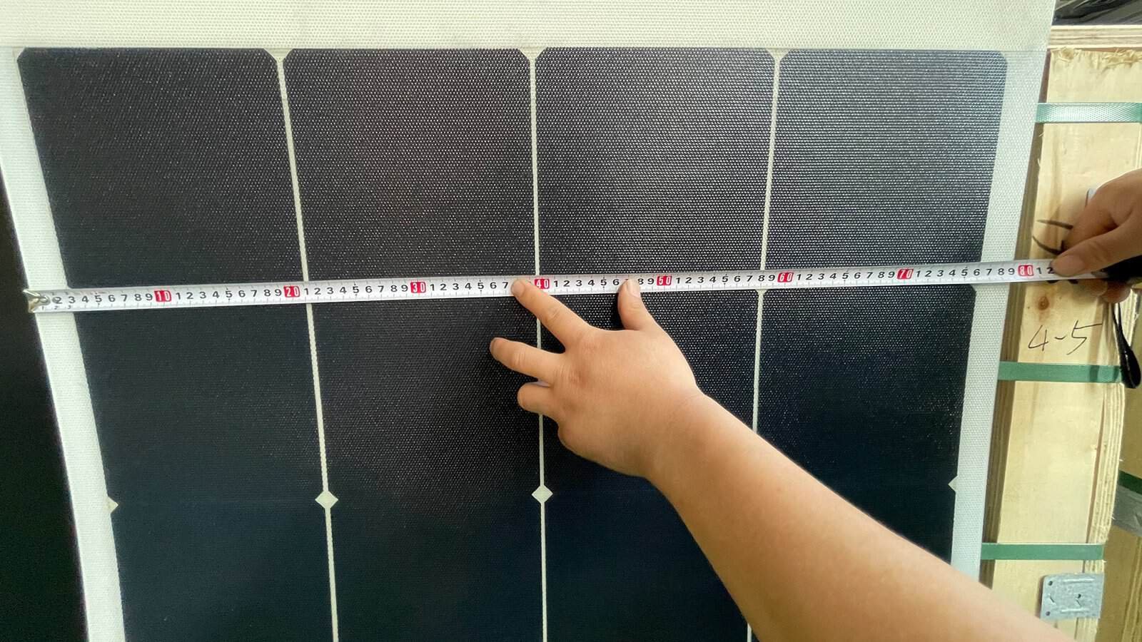
OEM & ODM Engineering Guide
Don’t start with watts. Start with the product, the space it lives in, and the battery it has to charge.
Short answer: to design a flexible solar panel around your product, fix the application, the electrical requirement and the mechanical envelope first, then let those three decisions determine the wattage. Wattage is an output of the design, not an input to it.
The working order is: Product → Electrical → Mechanical → Cell → Lamination → Prototype → Production. Skip a step and you usually pay for it in a second tooling round.
Five facts start any real quotation: the usable envelope, the minimum bend radius in millimetres, the system voltage and controller type, the exposure class, and the attachment method.
Why “I Need a 100 W Panel” Is the Wrong Place to Start
Most custom projects open the same way. A buyer asks for a 100 W flexible panel, then waits for a price.
The trouble is that “100 W” describes almost nothing. Voltage, current, outline, thickness, bend behaviour, cable exit — none of it is fixed by that number. Two panels can carry the same rating and still be useless in each other’s application.
Published data from one standard ETFE back-contact range makes the point better than any argument.
| Model | Power | Vmp | Imp | Voc | Isc | Size (mm) | W/m² |
|---|---|---|---|---|---|---|---|
| CLM-050M | 50 W | 23.6 V | 2.12 A | 27.3 V | 2.20 A | 670 × 405 | 184 |
| CLM-105M | 105 W | 16.6 V | 6.33 A | 18.9 V | 6.65 A | 1280 × 405 | 203 |
| CLM-120M | 120 W | 19.2 V | 6.29 A | 21.8 V | 6.80 A | 990 × 590 | 205 |
| CLM-160M | 160 W | 24.9 V | 6.43 A | 28.4 V | 6.71 A | 1265 × 590 | 214 |
| CLM-200M | 200 W | 30.7 V | 6.52 A | 35.0 V | 6.80 A | 1175 × 775 | 220 |
W/m² is calculated from the published outline dimensions, so it describes the whole module and not the cells inside it.
Look at the 50 W panel: 23.6 V. Now the 105 W panel, twice as powerful: 16.6 V. More watts did not mean more voltage, and only one of those two will charge a 12 V battery through a simple PWM controller. Wattage hides the decisions that determine whether a panel works at all.
Step 1: Start With the Product, Not the Panel
A flexible panel is not a rigid module made thinner. It is a laminate that inherits the mechanical and thermal life of whatever it is bonded to, so the survey comes first.
Ask where the panel sits, how the surface moves, what hits it, and what sits behind it. A backpack panel and a marine buoy panel share a technology and almost nothing else. One gets flexed daily and stored dry. The other is bonded down, salted, baked, and left alone for five years. Sort the application into an exposure class early — that class drives the laminate.
| Class | Typical products | Dominant stress | Design driver |
|---|---|---|---|
| Portable | Folding kits, backpacks, field chargers | Repeated flexing, handling, impact | Flex cycle life, edge protection |
| Mobile / attached | Vans, RVs, trailers, cargo boxes | Vibration, heat, one fixed curve | Thermal path, strain relief |
| Marine | Decks, biminis, buoys, sensor floats | Salt, UV, standing water, walk-on load | Moisture ingress, laminate symmetry |
| Structural | Shutters, awnings, facades, canopies | Long dwell, wind load, appearance | Colour stability, mounting interface |
Step 2: Fix the Electrical Requirement — Voltage Before Watts
Work backwards from the load. What voltage does the battery want? What controller is already sitting in the product? Voltage is the lever most buyers ignore, and it quietly decides how much energy the product actually harvests.
The 60-second datasheet audit
Before comparing quotes, check that each datasheet agrees with itself. Three ratios do this without needing to know anything about the cells inside.
| Check | Healthy range | What it catches |
|---|---|---|
| Vmp × Imp vs Pmax | Within about 1% | Copy-paste errors and invented rows |
| Vmp ÷ Voc | ≈0.80–0.88 | Optimistic Vmp, or a cell mix that is not what was quoted |
| Fill factor: Pmax ÷ (Voc × Isc) | ≈0.75–0.85 | Above 0.85 on a finished module deserves a flash report |
Applied to the five modules above, Vmp × Imp reproduces the nameplate to within 0.6% and Vmp ÷ Voc holds between 0.864 and 0.881. That consistency is a small but real quality signal.
Estimating cell count — and why it is only an estimate
You can also divide Voc by a per-cell figure to guess how many cells sit in series. Be careful here. Per-cell Voc is technology-dependent: roughly 0.66–0.69 V for mono PERC, 0.71–0.73 V for n-type TOPCon, 0.72–0.75 V for back-contact designs. PVEducation puts high-quality single-crystal silicon at up to 764 mV in the lab.
Move the assumption from 0.70 V to 0.75 V and the estimate for a 27.3 V panel drops from 39 cells to 36. Treat it as good to within two or three cells, and ask the factory for the real count.
Whichever figure you assume, one conclusion holds. The 50 W panel carries more series cells than the 105 W panel, because 27.3 V beats 18.9 V. It runs smaller cell segments, which is why its current stops at 2.12 A.
PWM or MPPT changes the panel you should build
A PWM controller pulls the array down to battery voltage. Everything above that point is thrown away. So a 12 V PWM system wants a panel with Vmp around 17–18 V — and nothing higher.
The penalty is real but frequently overstated. Victron’s technical paper works a 100 W, 36-cell case with an 18 V Vmp into a 13 V battery at 25 °C. It finds PWM harvesting 81 W against MPPT’s 100 W — about 19% less, not the 40% often quoted. The gap narrows as the panel heats up, because Vmp falls toward battery voltage.
The OEM rule: if you cannot control which controller the end user fits, design for MPPT and say so in the manual. If it ships inside your product, tune Vmp to it instead.
Voltage comes in steps, not on a dial
Cells are discrete, so each one you add or remove moves Voc by roughly three-quarters of a volt — and the extra cell may not fit your outline. On small panels this bites hard, which is why voltage and power must be negotiated together.
Working on a custom panel right now?
Send the envelope, the bend radius, the battery voltage and the controller type. We come back with a buildable outline and an honest electrical configuration.
Step 3: Mechanical Design Is Where the Watts Are Won or Lost
Cell efficiency gets the attention. On custom panels, outline geometry usually matters more.
Same area, different shape, 25% less power
Take two outlines of identical area, both 0.60 m², allow a 15 mm inactive border and 2 mm between cells, then tile them with full 182 mm (M10) cells.
A 1000 × 600 mm panel fits five cells by three, so fifteen. A 1200 × 500 mm panel fits six by two, so only twelve. Same area, same cells, same encapsulant. At a mainstream n-type cell power of roughly 7.9 W per 182 mm cell, that is about 119 W of cell against 95 W. The shape simply wasted a strip of silicon-width that could not be filled.
Read that carefully when you check a quotation, because those figures are sums of cell power rather than module power. The cell-to-module ratio for mainstream glass modules has exceeded 100% since 2021. Light scattered inside the laminate is recycled back onto the cells by total internal reflection at the glass-air boundary. Flexible ETFE laminates capture less of that gain. AGC’s technical data puts the refractive index of ETFE at 1.40, below glass at about 1.52, which opens the critical angle and lets more of that scattered light escape. Expect a finished flexible panel nearer 90% of its cell sum, so roughly 107 W and 86 W here. The 25% gap between the two outlines is the point, and it survives either way.
Now halve the cells, to 182 × 91 mm. The awkward outline fits six by five: thirty half cells, exactly matching the good outline. It recovers the full cell total on no extra area and no better cell. The tiling unit simply got smaller.
Worth asking for: when your outline is fixed and awkward, have the factory re-tile it with half or quarter cells before you accept a lower wattage. Cutting the cell smaller usually costs less than enlarging the product.
Small panels are less dense, and the reason is geometry
Look again at the model table. Power density climbs from 184 W/m² on the smallest panel to 220 W/m² on the largest. That is a 19% spread inside one family, using the same cells and the same laminate.
The cause is perimeter. Border margin is a fixed width, so it eats a bigger fraction of a small panel. A 15 mm border leaves 88.4% of the 670 × 405 mm outline usable, but 93.7% of the 1175 × 775 mm one. So do not benchmark a 50 W custom panel against a 200 W catalogue panel on W/m² and call the small one badly built.
A quick sizing formula before you commit
Sanity-check any proposal with this:
Estimated Wp = usable area (m²) × coverage factor × whole-module W/m²
Coverage factor: 60–70% conservative, 75–85% a good design target, 85–95% for a heavily optimised custom outline. For back-contact crystalline flexible panels, use 190–210 W/m² for mid-size formats and drop toward 185 W/m² on small ones.
A 0.90 m² usable area at 85% coverage and 200 W/m² gives about 153 W, while the same area at 65% coverage gives 117 W. That 36 W gap is what a properly designed outline is worth.
A warning worth repeating: never size an area using cell efficiency. A 26% cell at 85% coverage lands nearer 20% once module losses are counted.
Step 4: Ask for Bend Radius in Millimetres
The flexible panel market advertises in degrees: “bends up to 240°”, “180° flexible”, “flexes 30 degrees”. Treat all of it as marketing copy.
An angle is not a mechanical specification. Spread the same angle over a longer panel and the bend becomes far gentler, so the figure says nothing about strain in the cell or the interconnect. Minimum bend radius does.
Published radii span roughly ten to one across the market. Around 300 mm sits at the flexible end, thin-film products cluster near 500 mm, and reinforced constructions reach about 3,000 mm. “Flexible”, used alone, is meaningless.
There is a documented trap here, and it comes from a well-regarded product rather than a bad one. The HeliaSol 436-2000-AFA datasheet, Rev 09 leads with a 50 cm minimum bending radius for unidirectional curves, while the product label reproduced inside the same PDF prints 20 cm. One document, one revision, 2.5 times apart.
That does not make the product unreliable. It shows how easily a headline, a label and a spec table drift apart. Put the radius you designed against into the purchase order, naming the document revision and date.
Ask for these four, in writing:
- Minimum bend radius in millimetres
- The bending axis — along the cell string, or across it
- Whether the bend is set once at installation or repeated in service
- Flex cycle count, if repeated
If the panel flexes repeatedly, ask for test evidence rather than a radius claim. The 2021 edition of IEC 61215 added test methods for flexible modules, including the bending test MQT 22, which cycles a module over a drum while monitoring continuity. Custom panels are rarely certified as catalogue models, so what you want is data on your own construction: an MQT 22-style flex report with electroluminescence images before and after.
Step 5: Choosing the Right Solar Cell for a Flexible Panel
Cell selection comes fifth. By this point the outline and the voltage have already narrowed your options, which is exactly as it should be.
Back-contact cells suit premium flexible work for one specific reason. Moving the metallisation to the rear leaves the front face free of busbars and gridlines, which looks cleaner and puts more of the surface to work. On a consumer product where the panel is visible, that matters.
Why whole-module W/m² beats cell efficiency
Cell efficiency flatters. Aperture efficiency flatters. Whole-module W/m² tells you what actually fits your envelope.
| Flexible technology | Whole-module W/m² | Best fit |
|---|---|---|
| n-type back-contact c-Si | ≈185–220 | Tight envelopes, premium appearance |
| Glass-free mono PERC c-Si | ≈170–180 | Cost-led volume programmes |
| CIGS thin film | ≈120–160 | Very light, rollable, large areas |
| Organic PV film | ≈57–63 | Ultra-light surfaces, hot climates |
Each band is calculated from rated power over outline dimensions, so small formats sit at the bottom and large ones at the top. None of it is a ranking. Organic film publishes a 0.00%/°C power coefficient from 25 °C to 65 °C and weighs under 2 kg/m², which can outweigh raw density on an ultra-light or very hot surface — though it carries a ±10% power tolerance, against the tighter positive-only tolerances typical of silicon. Choose on fit.
Watch for the aperture-efficiency gap, because efficiency is sometimes quoted over the active area alone. Work an example. The organic film above is rated 50–55 W over a 2000 × 436 mm outline, or 0.872 m², giving a whole-module efficiency of 5.7–6.3% against a published aperture figure of 7.2–8.0%. That gap is about a fifth of the answer. Ask which area a figure refers to before you plan an envelope around it.
An honest word on shading
Back-contact cells do handle mild shading better. We are not going to overstate by how much. A TÜV NORD simulation study reported by pv magazine found the advantage holds while three or fewer cells are shaded across different substrings. Past about four cells, both back-contact and TOPCon lose roughly half their output.
So judge the obstruction, not the cell. A rail, an antenna, a pipe — anything smaller than the panel — and back-contact earns its place. Anything bigger, and no cell technology will save you. Move the panel.
On small custom panels, bypass diode zoning often buys more than cell choice does, so ask how many diodes the junction box carries and where the boundaries fall.
Step 6: What a Five-Layer or Nine-Layer Laminate Actually Buys
“Five-layer” and “nine-layer” are useful shorthand and terrible specifications. What matters is the set of jobs the stack has to do: transmit light, encapsulate, reinforce, carry the cell plane, resist moisture, and balance stiffness.
A thicker stack buys resistance to thermal cycling, vibration, bending stress and moisture ingress. It also adds weight — about 3.6–3.9 kg/m² standard against 4.4 kg/m² reinforced, across a real ETFE back-contact range. That is a trade, not a free upgrade. Three things are worth knowing before you specify one:
- Symmetry is about stiffness, not mirrored layer names. An unbalanced stack curls with temperature and puts the cells off the neutral axis.
- A laminated flexible panel has no butyl edge seal, because there is no glass cavity to seal. Moisture crosses the faces rather than the rim — AGC measures ETFE moisture permeability at 1.3 g/m² per 24 hours through 0.1 mm — so perimeter protection comes from encapsulant flow and edge margin instead. Semi-rigid builds with a backing plate can carry a seal, so ask which structure you are getting.
- ETFE is the front sheet doing most of the durability work. AGC’s Fluon ETFE film is produced between 12 and 250 µm. AGC Chemicals Americas reports transmittance above 90% and no deterioration after 16,000 hours of accelerated weathering, which they equate to more than 30 years outdoors.
The Step Almost Everyone Skips: Mounting Sets the Operating Temperature
This rarely appears in flexible panel literature, and it may be the most valuable thing on this page. A panel bonded flat to a surface has no rear airflow at all. The Sandia Array Performance Model publishes separate thermal coefficients for exactly this case. The pvlib parameter set defines it as no air flow contacting the rear surface, typical of building-integrated PV or systems laid flat. The coefficients come from Sandia’s PVPMC.
Run the model at 900 W/m², 30 °C ambient and 1 m/s wind, across the three published mounting cases.
| Mounting | Cell temp. | What it looks like on a product |
|---|---|---|
| Open rack | ≈56 °C | Free-standing frame, air on all sides |
| Close mount | ≈75 °C | Spacers or a rail giving a shallow gap |
| Insulated back | ≈82 °C | Bonded flat to a roof, deck or panel |
That ladder carries a warning. Bonding costs about 25 °C against open rack, worth roughly 6–7% of output at the −0.26 to −0.29%/°C range current n-type and back-contact modules publish. A shallow gap recovers only about 7 °C, or some 2%. Most of the penalty comes from being attached to a surface at all — not from the last few millimetres of air.
Two consequences follow for your design brief.
First, a datasheet NOCT or NMOT figure never describes a bonded panel, because those conditions are measured with the back side open.
Second, “leave an air gap” is oversold as a fix. It is worth having, and a sealed cavity is worth avoiding — specify cross-flow with open ends — but budget for the heat rather than assuming a spacer removes it.
Honest limit: the closest published Sandia case is a glass/cell/polymer module, not an ETFE laminate. Direction and order of magnitude hold. The decimals do not.
Step 7: Prototype — Test More Than Pmax
A prototype that only proves power output has proven very little. Treat the table below as an acceptance sheet.
| Area | Check | Why it matters |
|---|---|---|
| Electrical | Pmax, Voc, Isc, Vmp, Imp against the flash report | Confirms the string configuration you agreed |
| Cell integrity | EL image before and after bending to spec radius | Catches microcracks a flash test cannot see |
| Mechanical | Outline, thickness, weight, eyelet positions | Millimetres decide whether it fits the tooling |
| Fit | Mount it on the real product, not a bench | Reveals cable clash and clearance errors |
| Thermal | Rear surface temperature as actually mounted | Validates the derate you designed around |
| System | Charging into a battery at 40–60% state of charge | A full battery hides real panel performance |
Test charging on a partly discharged battery. A controller in absorption or float deliberately reduces current, and plenty of “underperforming panel” reports turn out to be full batteries.
Step 8: From Prototype to Repeatable Production
A successful prototype is not automatically a production design. One panel proves the concept. A thousand prove the process. Lock these down before the first run:
- Final drawing with dimensional tolerances stated, not implied
- Cell layout, cell format, series configuration and diode zones
- Electrical spec with the power tolerance and binning rule
- Laminate stack, by function and material, with suppliers fixed
- Cable length, gauge, connector type and junction box IP rating
- QC plan: flash test coverage, EL sampling rate, visual criteria
- Change control — who must approve a material substitution
That last line matters more than it looks. Swap an encapsulant, a front sheet or a cell supplier quietly, and bending behaviour and moisture performance both move while every number on the datasheet stays put. Name the materials in the contract.
The Twelve-Line Product Brief
Copy this into your next enquiry. It replaces roughly three rounds of email.
- What is the product, and where does the panel sit on it?
- Usable envelope in mm, after obstructions
- Is the surface flat, single-curved or compound-curved?
- Minimum bend radius in mm, and the axis
- Bend set once, or repeated? Rough cycle count if repeated
- Battery voltage and chemistry
- Controller type — PWM, MPPT, or built into your product
- Target power, plus the minimum you can live with
- Environment: UV, salt, submersion, vibration, walk-on load
- Attachment method and cable exit position
- Colour and appearance requirements
- Annual quantity and first-order quantity
Answer those twelve and a factory can propose a real layout, voltage configuration and laminate on its first reply.
Key Takeaways
- Wattage is an output of the design; envelope, voltage and environment are the inputs.
- Equal power does not mean equal voltage — check Vmp before anything else.
- Outline shape can move output by 25% at identical area. Half-cut cells often recover it.
- Bend angle is marketing. Bend radius in millimetres, with axis and cycle count, is a spec.
- Bonding costs about 25 °C against open rack, near 6–7%. A gap wins back a quarter of that.
- Custom panels are rarely certified as catalogue models. Ask for data on your own construction.
Frequently Asked Questions
Can I just ask for a 100 W custom flexible solar panel?
You can, but you will get a guess. A 100 W panel can be built at 16 V or 30 V, in a dozen outlines, with very different bend behaviour. Give the envelope, the bend radius and the battery voltage. The wattage follows.
How much power fits in my available space?
Multiply usable area in m² by a coverage factor of 0.75–0.85, then by 190–210 W/m² for a back-contact crystalline flexible module. A 0.9 m² usable area realistically supports 130–160 W. Small formats land lower.
What is a realistic minimum bend radius for a flexible panel?
Around 300 mm is achievable for a well-built crystalline flexible laminate. Published values run from roughly 300 mm to 3,000 mm, so ask for the figure and the axis rather than a degree claim.
Why does my flexible panel produce less than its rating?
Usually heat, angle and controller type — not a fault. A bonded panel lying flat runs hot and points at the sky rather than the sun. Our breakdown of flexible panel output in the real world walks the full derate chain.
What is the minimum order quantity for a custom flexible solar panel?
At Couleenergy, custom ETFE back-contact builds start at 100 pieces, with a sampling round before that. Changes that need no tooling — outline, cell layout, cable position, connector — cost far less than changes to the laminate stack. Sample turnaround and lead time are confirmed in your quotation, since both move with cell format and stack.
What does a custom flexible solar panel project actually cost me in time?
The variable is prototype rounds, not factory speed. A complete brief usually gets you to one. A wattage-only enquiry often means two or three, because the first sample answers a question nobody had defined.
Do back-contact cells really help with shading?
In mild shading, yes. Published simulation work puts the advantage at three or fewer shaded cells across substrings; beyond about four it disappears. Judge by whether the obstruction is smaller or larger than the panel.
How this article was checked
Power-density and border-overhead figures were calculated from published outline dimensions and electrical data, then checked arithmetically. Layout comparisons assume a 15 mm inactive border and 2 mm inter-cell gaps. Cells are pseudo-square, so rectangular tiling slightly overstates active area without changing the cell count.
Two claims were corrected in review and are worth naming. An earlier draft said the data confirmed its cell-count estimate; it does not, because snapping a division to the nearest whole cell makes almost any assumed per-cell voltage look self-consistent. And an earlier mounting section implied a gap recovers most of the bonding penalty, when the published close-mount case recovers about a quarter of it.
Two figures stay deliberately unsettled. The Sandia thermal cases use glass/polymer and glass/glass modules as the nearest published proxies for an ETFE laminate, and the close-mount coefficients exist only for glass/glass. The shading result comes from a simulation, not a field trial.
Last reviewed: September 2026.
Sources
- Sandia PVPMC — module temperature model — the a and b coefficients used for the bonded-versus-vented comparison
- pvlib — SAPM cell temperature parameters — defines the insulated-back case as no air flow contacting the rear surface
- Victron Energy — PWM or MPPT technical paper — the worked 81 W versus 100 W case
- PVEducation — open-circuit voltage — per-cell Voc limits behind the cell-count estimate
- HeliaSol 436-2000-AFA datasheet, Rev 09 — the 50 cm versus 20 cm bend-radius example, and the organic PV figures quoted
- AGC Chemicals Europe — Fluon ETFE film — the 12–250 µm production range
- AGC — Fluon ETFE technical data (PDF) — refractive index 1.40 and moisture permeability
- AGC Chemicals Americas — Fluon ETFE film — transmittance above 90% and the 16,000-hour weathering test
- pv magazine — TÜV NORD back-contact shading study
- IEC 61215-1:2021 — the 2021 edition that introduced the MQT 22 bending test for flexible modules
- TaiyangNews / ITRPV — cell-to-module gains and losses — why glass modules now exceed 100% CTM
- pv magazine — M10 182 mm wafer standardisation — the cell format used in the layout examples
Start With the Product
Tell Us About Your Product. We’ll Engineer the Panel.
Couleenergy builds custom ETFE back-contact flexible modules, rigid back-contact panels and dual-glass BIPV products. Custom size, power and shape, from 100 pieces.
What you get back: a cell layout drawn to your envelope, an electrical configuration matched to your controller, a laminate matched to your environment, and a prototype plan naming the tests we will run.
Email info@couleenergy.com or call +1 737 702 0119 for project-specific advice. Send the twelve lines above and we reply with engineering, not a catalogue.
Related reading: flexible solar panels · back-contact modules and custom solutions


 English
  Español
  Français
  Deutsch
  Русский
  العربية