
Quick formulas say one number. The roof usually says another. Here is how to find the real count, and how to get more power from the space you have.
The problem
The number on the calculator is almost always too high
Most online guides give you one simple rule. Take your roof area, divide it by the area of one panel, and you have your answer. It is fast. It is also wrong on nearly every real house.
Here is a typical case. Take a rectangular roof face that is 10 m long at the eave and 5.5 m from eave to ridge. That is 55 m². A common 440 W module measures about 1.76 × 1.13 m, so it covers about 2 m². Divide one by the other and you get 27 panels.
Now lay the panels out for real. Keep the edges clear. Leave the ridge free. Add small gaps for clamps. Suddenly the same roof holds between 12 and 21 panels. The answer depends on how you arrange them and which local rules apply.
That gap changes system size, inverter choice and the whole business case. For installers, it changes what you promise at the kitchen table.
The good news? Getting a realistic count no longer needs a CAD license or a ladder. A new free tool can do it from a single photo. Let’s look at how it works, where it stops, and what you can do with the result.
The tool
A free tool that counts modules from a roof photo
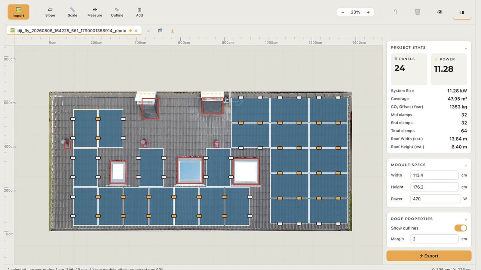
In September 2026, the German company Tegrona released Tegrona Lite, free software that plans a PV layout directly on a picture of a roof. pv magazine covered the launch and described it as a tool for the first site visit. The goal is a quick, credible module count without measuring tape or drawing software.
The workflow is simple:
- Load an image. A drone shot, a street photo or a roof plan all work.
- Mark the roof face. You click three or four points around the surface you want to use.
- Draw no-go zones. Chimneys, dormers, skylights and vents get their own exclusion areas.
- Let the software fix the perspective. More on this below.
- Pick a module. Enter its size and power, then let the tool fill the roof.
- Export. You get a PDF or PNG sheet with the layout drawn over the original photo.
Why roof tiles make a good ruler
Photos taken from the ground are distorted. The eave slopes, and tile rows seem to run together toward a far point.
Tegrona’s idea is simple. Tile rows and columns are parallel on the real roof. So the lines they form in the photo reveal the vanishing points. From those, the software calculates how to “flatten” the image. After correction, the eave sits level and module rows line up with it.
The tiles also give the scale. You choose the tile type, and the tool counts the tiles it sees. Because each tile model has a known coverage size, the software can turn pixels into meters. The built-in catalog includes common German profiles, and you can add other tiles by their coverage size. If the tiles do not help, one known size works too, such as the width of a roof window.
Tile lines also help on trapezoid and triangle faces, which four corner points alone cannot correct.
What happens after the scale is set
The layout engine places modules in portrait, landscape, or a mix of both. On roof faces that get narrower toward the ridge, it can shift rows sideways and rotate modules to use leftover space. You can set edge distances too.
Every time you change something, the numbers update: module count, total power, covered area, and even the number of middle and end clamps. That clamp count is a nice touch for anyone who has to prepare a parts list.
Two more points stand out. First, all processing runs on your own device. Photos are not uploaded, so location data stored in drone images stays private. Second, there is no account, no trial timer and no module limit. Desktop versions run on macOS 14+ and Windows 10+, and a web version runs in the browser in 11 languages.
Six common traps
Why “roof area ÷ panel area” overcounts
Photo tools, satellite tools and manual sketches all fight the same six problems. Knowing them helps you judge any number you see.
1. Setbacks take the edges
Fire and building codes keep strips of roof clear. In the US, the residential code in IRC section R324.6 and the matching fire code rules set ridge setbacks by coverage. According to the NFPA, arrays covering up to a third of the roof need 18 inches (457 mm) at the ridge. Larger arrays need 36 inches (914 mm). In homes with an automatic sprinkler system, the 18-inch setback applies up to two thirds coverage.
Three details catch people out. First, coverage is measured against the whole roof in plan view, not the one face you are filling. Second, the code asks for at least two 36-inch pathways from eave to ridge, on separate roof planes. Every plane with modules needs one on it or next to it. Third, these rules only apply to roofs steeper than 2:12 (about 9.5°). Many states and towns amend them, so the local building department has the final word.
In Europe, the driver is often wind. Roof edges and corners see much higher suction than the middle. The wind code EN 1991-1-4 (section 7.2.5) splits a pitched roof into zones with different pressure values. The edge and corner zones grow with the size of the building. Planners either keep modules out of these zones or add extra fixings there. Your local rules and the mounting maker’s manual decide the exact distance.
2. Obstacles cost more than their own size
A chimney is not just its footprint. It needs clearance around it, and in a grid layout it can block part of a row and a column at once. One vent in the wrong place can cost two modules.
3. Rectangles do not tile perfectly
Modules come in fixed sizes. The roof does not. There is almost always an unused strip along one side. It can be anything up to just under one module width, so another full module never fits.
4. Orientation changes the count
Portrait and landscape give different results on the same roof. There is no universal winner. It depends on the usable width and height, as the example below shows. Orientation also changes where clamps sit on the frame. Module manuals set clamping zones, and some zones carry a lower load rating. Check the manual before you commit to a layout in a windy or snowy area.
5. Gaps add up
Clamps need a small space between modules, usually 10 to 25 mm depending on the clamp. At 20 mm, a row of eight loses 14 cm. It sounds tiny. Sometimes it is exactly what pushes the last module off the roof.
6. A flat map view measures the footprint, not the slope
A simple map drawing sees the roof from straight above. That view shows the horizontal footprint. The real sloped surface is larger. On a 35° roof, the slope is about 22% longer than it looks from above. On a 45° roof it is about 41% longer. Some map calculators say this openly and treat the footprint as a cautious starting point. Tools that build a 3D roof model, and photo tools that measure on the roof plane, avoid the problem.
| Roof pitch | True slope length vs. map footprint | Hidden slope per 5 m of footprint |
|---|---|---|
| 20° | × 1.06 | 0.32 m |
| 30° | × 1.15 | 0.77 m |
| 35° | × 1.22 | 1.10 m (almost one landscape row) |
| 45° | × 1.41 | 2.07 m (more than one portrait row) |
Worked example
One roof, six answers
Let’s go back to our 10 × 5.5 m roof face on a simple gable house. The other face points north and stays empty. We start with simple planning margins, the kind used where no fire-code pathway applies. That means 30 cm clear at both sides and the eave, and 457 mm at the ridge. That leaves a usable box of 9.40 × 4.74 m, about 81% of the face.
The module is a common 108 half-cell format, 1,762 × 1,134 mm, rated around 440 W (about 22% efficient). Gaps are 20 mm. Every layout below is drawn to scale.
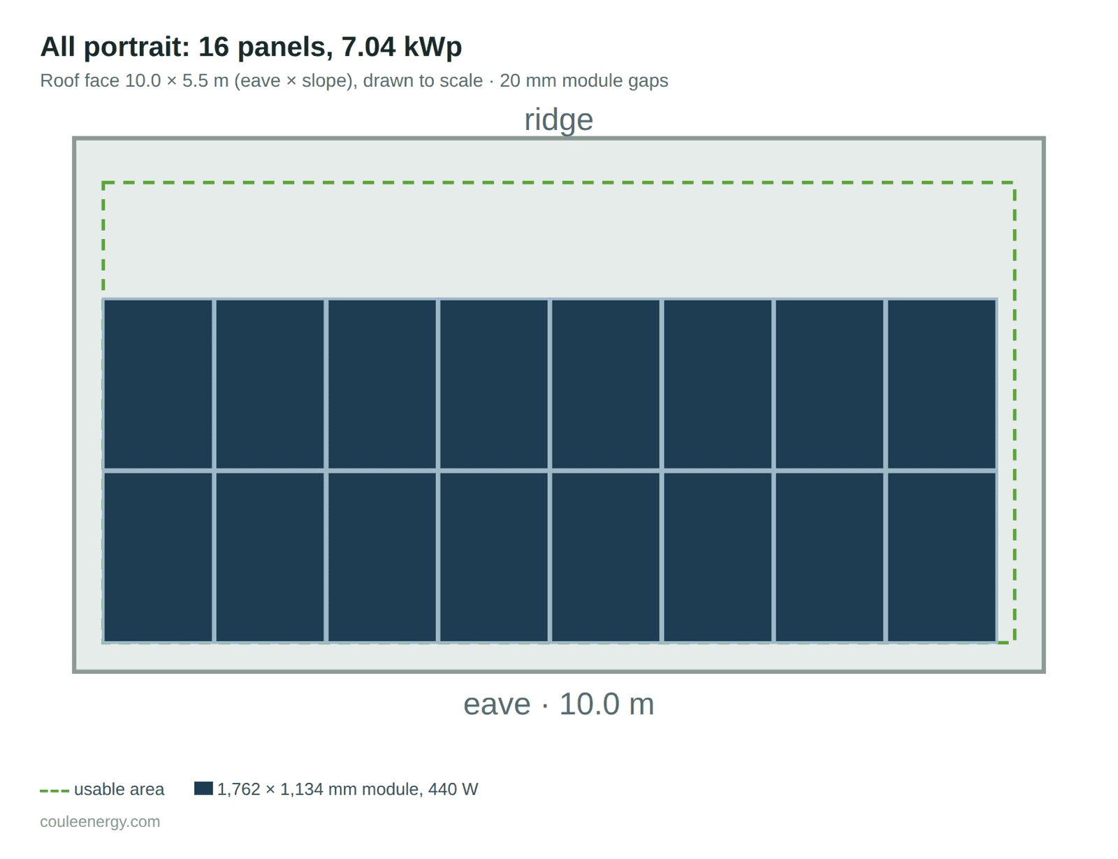
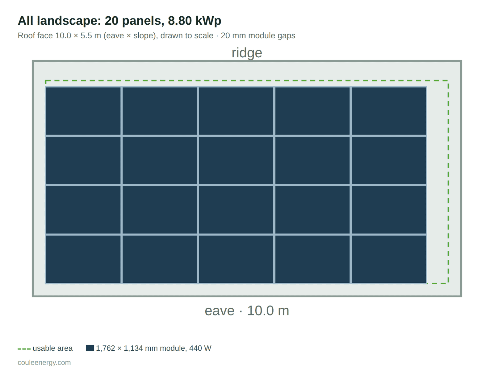
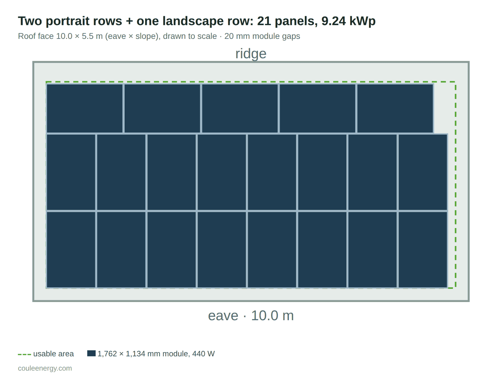
The mixed layout wins. Two portrait rows use 3.54 m of height. That leaves just enough room for one landscape row on top. This is exactly the kind of move good layout software makes for you.
Now change one rule. Suppose the ridge strip grows to 36 inches (914 mm). The usable height drops to 4.29 m.
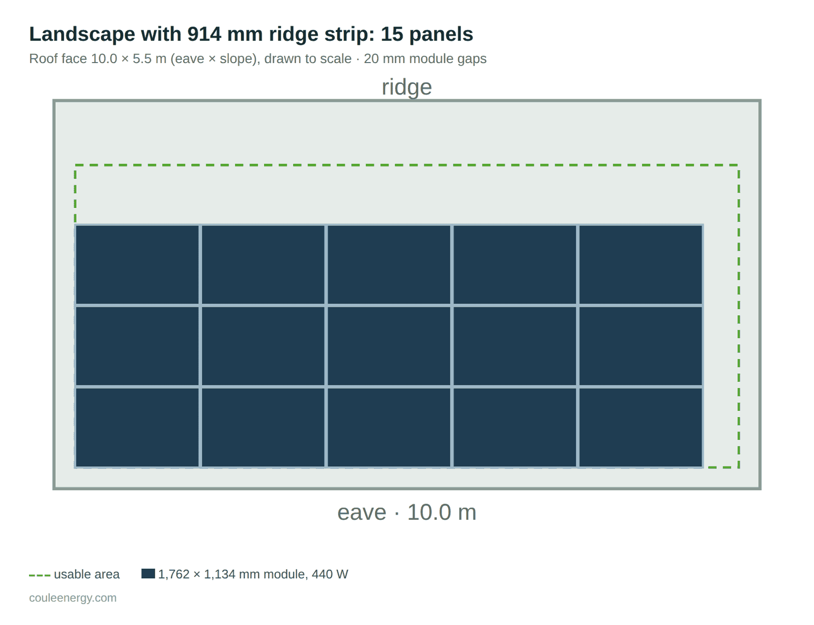
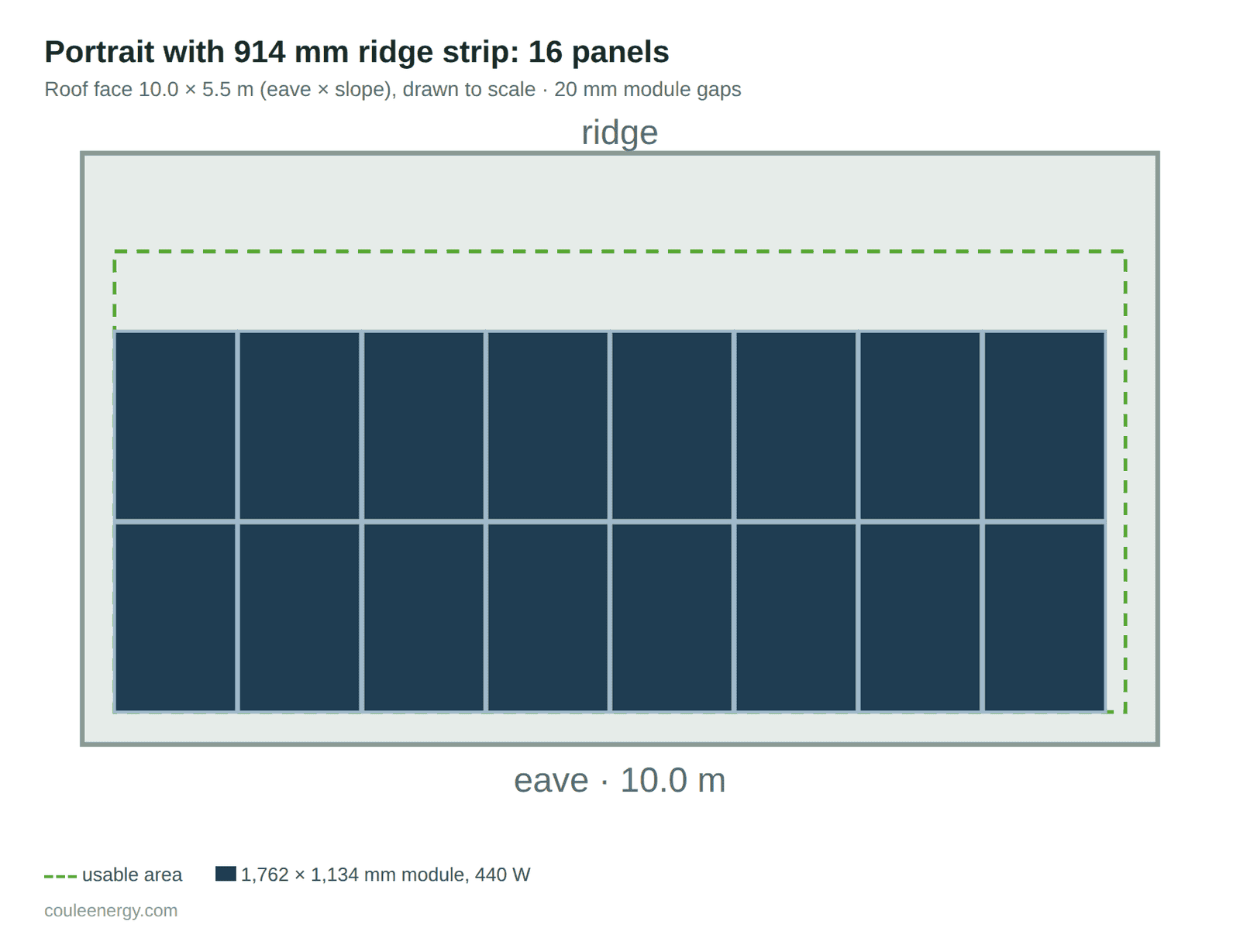
Look what happened. Landscape went from best to worst. Portrait did not change at all. One rule flipped the answer. That is why a single “panels per m²” figure can never replace a real layout.
The same roof under the US residential code
Now apply the IRC to our gable house. It has only two roof planes, so one of the two required pathways must sit on the solar face. We place a 914 mm pathway along one side, from eave to ridge. The usable box shrinks to 8.79 × 4.74 m.
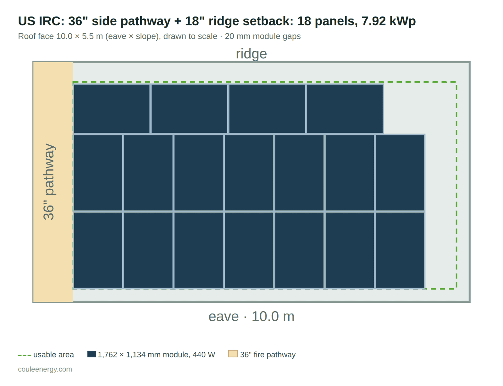
The best fit is a mix again: two portrait rows of seven plus a landscape row of four. And here is a twist. If both faces are the same size, those 18 modules cover about 32.7% of the whole roof in plan view, just inside the one-third limit. So the smaller 18-inch ridge setback still applies. Add one more module and the array would need 36 inches, which would cost a full row. In the US, the setback and the module count decide each other.
| Scenario | Portrait | Landscape | Mixed |
|---|---|---|---|
| Simple margins, 457 mm ridge strip | 16 | 20 | 21 |
| Simple margins, 914 mm ridge strip | 16 | 15 | 16 |
| US IRC: side pathway + 18″ ridge | 14 | 16 | 18 |
| US IRC: side pathway + 36″ ridge | 14 | 12 | 14 |
Note that the 20- and 21-module layouts would cover more than a third of this roof. Under the US code, a house without sprinklers would then need the 36-inch ridge setback, so those two counts are not available there.
A better formula for quick estimates
You will still want a fast number before you open any tool. Use this version instead of the simple divide:
Power (kWp) = panels × module watts ÷ 1,000
For the usable share, our example landed at 81% with simple margins and 76% under US pathway rules. Use something in that range for a clean face, and go lower on busy roofs with vents and dormers. The fill factor covers gaps and awkward leftovers. Our layouts filled between about 64% and 94% of the usable box, and the better layouts sat above 85%. So 80–85% is a fair planning value once you have tested orientations. For the US case, 55 m² × 0.76 × 0.85 ÷ 2.0 m² gives about 18 panels, which matches the drawn layout.
Then check the result with a layout. A photo tool, a satellite tool like Google’s Project Sunroof, or a sketch on grid paper all work. The formula tells you the ballpark. The layout tells you the truth.
Get more from the same roof
Five ways to fit more power on the same roof
Once you know the real count, the next question is simple. Can you do better? Usually, yes.
1. Mix orientations
As the example showed, a mixed layout added one module over the best single orientation. Always test portrait, landscape and a mix. Good tools do this in seconds.
2. Shift rows on odd shapes
Hip roofs and trapezoid faces get narrower toward the top. Shifting each row sideways, instead of stacking them in a strict grid, often saves a module per row.
3. Choose watts per square meter, not watts per panel
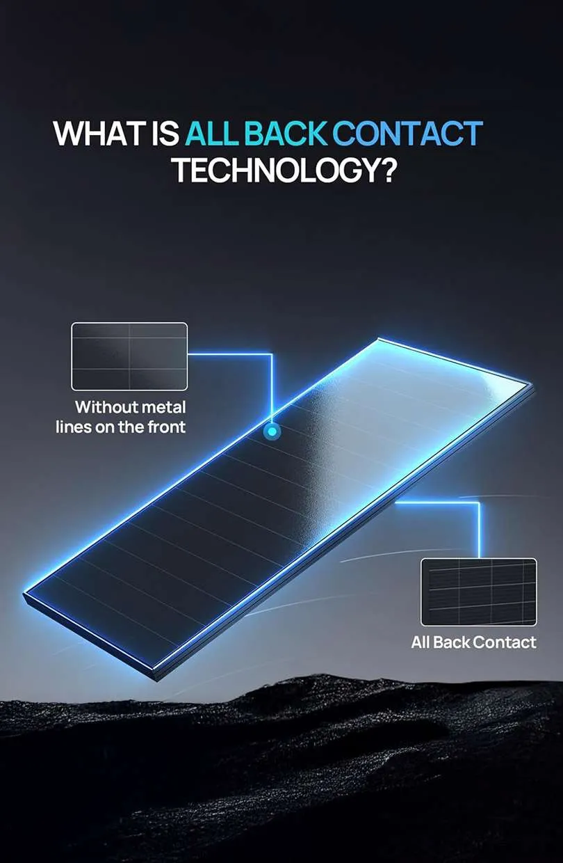
Two modules can have the same size and very different power. What matters on a tight roof is power density, in W/m². Our example module gives about 220 W/m², or 22% efficiency. Back-contact (BC) cells move all the metal contacts to the rear, so no grid lines shade the front, and that pushes density up. Here is the arithmetic: a module of the same size at 24% efficiency would be rated about 480 W instead of 440 W. That is 9% more power from the same roof, which on our US layout is worth more than one extra module.
4. Fill the leftover strips with custom sizes
Remember the unused strip beside the last full module? Standard modules come in a few fixed sizes, so that strip usually stays empty. A custom-size module can be built to fit it. The same goes for space between dormers, narrow areas under a ridge, or a band along a flat-roof parapet.
This is where manufacturers who build to order earn their place. At Couleenergy, we design custom solar panels around the space, not the other way around. Length, width, cell count, voltage and color can all change to suit the roof.
5. Use lighter modules where weight is the limit
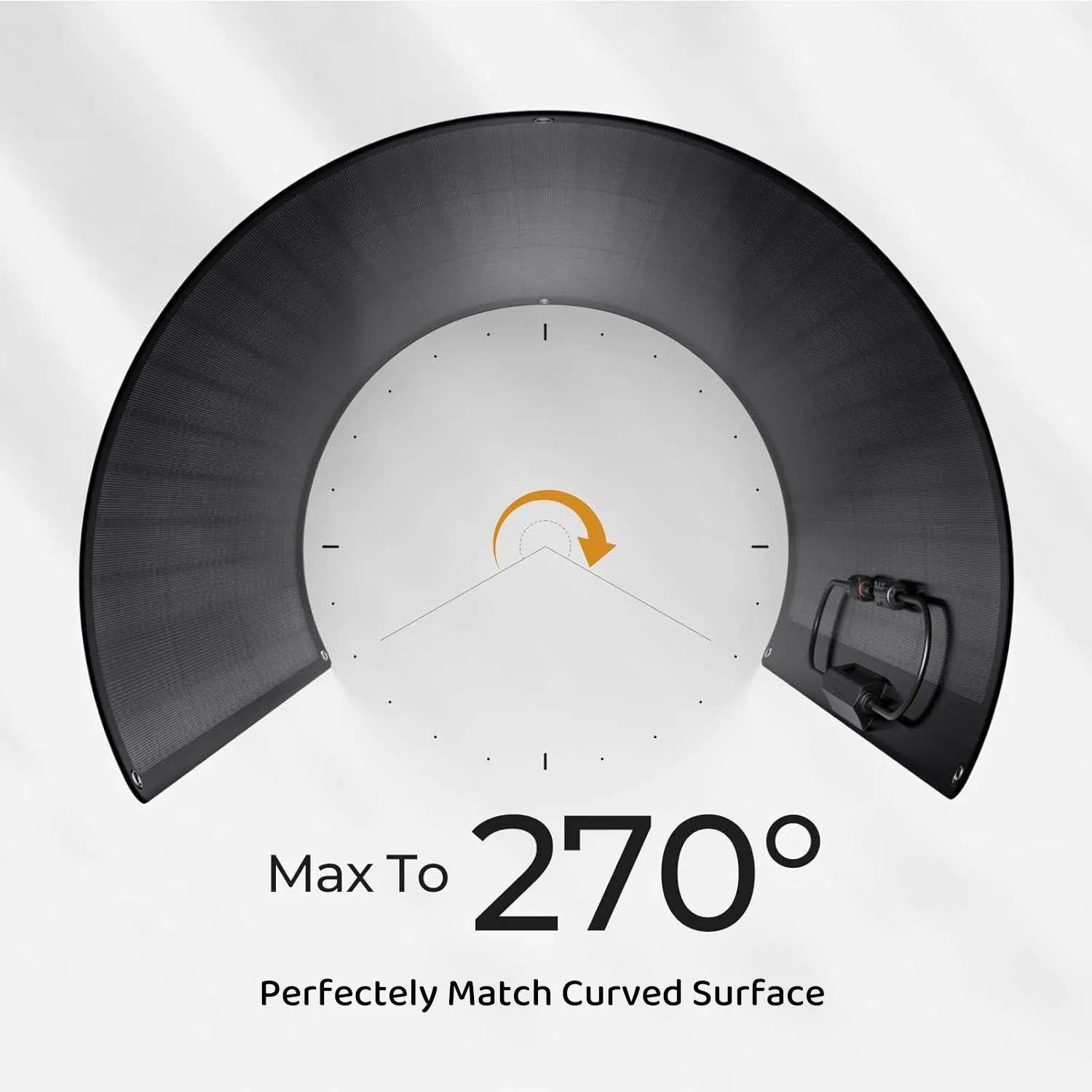
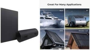
Sometimes the space is there but the structure is not. Old barns, carports, metal sheds and some flat roofs cannot take the load of framed glass modules. Lightweight flexible or semi-rigid modules open these areas up. They can also follow gently curved surfaces. Always have the roof checked first, and use a mounting method the roof can safely carry. On buildings, the module and mounting must also meet local listing and fire-classification rules, so confirm them before you plan around a lighter product.
What a photo count cannot tell you
A layout is a promise about space, not about energy. Before any quote becomes a contract, the design still needs these checks:
- Shading. Trees, chimneys and neighbors cast shadows that move with the seasons. A module that fits may still earn very little.
- Orientation and tilt. A north-facing face in Europe may fit many panels and still be a poor choice.
- String design. Module count must match the inverter’s voltage window. Sometimes you drop a module to make strings work.
- Structure. Rafters, battens and fixing points must carry the load, including snow and wind.
- Local approval. Setbacks, fire classes, heritage rules and grid limits vary by town and country.
- Real needs. The biggest array is not always the right one. As EnergySage points out, output also depends on sunlight and panel choice, not just area.
Think of it as a funnel. The photo tool gives a fast count on day one. Design software handles yield and strings. An engineer signs off the structure.
Who gets the most from photo-based layouts
Installers can show a credible count on the first visit, then confirm key sizes on site. Distributors can help smaller installers turn “about 20 panels” into a parts list. Architects and developers can test roofs before paying for surveys. Product makers can apply the same logic to RV roofs, boat decks and carports, which are roofs with fixed space and fixed obstacles too.
Next step
Your roof has leftover space. Let’s design modules for it.
A photo tool shows you what standard modules can do. If the result leaves empty strips, odd corners or weight limits, a custom module can often close the gap. Couleenergy builds back-contact modules in custom sizes, rigid or flexible, for distributors, installers, OEMs and project developers across North America and Europe.
Send us these five things, and our engineers will reply with a module proposal:
- A photo or plan of the roof or surface, with the free Tegrona Lite layout if you have one.
- The usable dimensions, or one known measurement we can scale from.
- Obstacles and setbacks you must respect.
- Your target power, voltage or inverter, if known.
- The roof type and any weight limit.
We do not publish prices, because every custom build is different. Tell us about your project and we will quote it properly.
Email: info@couleenergy.com
Phone: +1 737 702 0119
Frequently asked questions
How many solar panels fit on an average roof?
There is no true average, because shape and rules matter more than size. As a rough guide, a clean roof face keeps about 75–80% of its area usable, and standard modules cover about 2 m² each. So a 50 m² face often holds somewhere in the mid to high teens. Always confirm with a layout.
Is a photo accurate enough to plan a solar layout?
For a module count, often yes, if the photo shows clear tile rows or one known size to set the scale. It is not enough for final design. You still need measurements on site, a shading study and a structural check before installation.
Should solar panels go in portrait or landscape?
Test both. The best choice depends on the usable width and height after setbacks. In our example, landscape won with a 457 mm ridge strip and lost with a 914 mm one. A mix of both often beats either.
How far from the roof edge must solar panels be?
It depends on local code. Under the US residential code, ridge setbacks are 18 or 36 inches depending on coverage and sprinklers, and 36-inch pathways run from eave to ridge. In Europe, wind edge zones and the mounting manual usually decide. Ask your local authority before finalizing.
Can custom-size panels really add power to a full roof?
Yes, when the roof has leftover strips or odd shapes that standard sizes cannot fill. A custom module sized to the gap turns unused space into extra watts. Send us your layout and we will check what fits.
Sources
- pv magazine: Free software calculates how many solar modules fit on a rooftop from a photo (26 Sep 2026)
- Tegrona: Tegrona Lite and Tegrona product pages and FAQ
- NFPA: Residential solar panel requirements
- UpCodes: IRC R324.6 roof access and pathways
- Harford County, MD: IRC R324 text, including R324.6.1 pathways
- Eurocode Applied: EN 1991-1-4 wind pressure on duopitch roofs (section 7.2.5)
- SolarQuotes: Solar panel clamping zones
- Mapscaping: How many panels fit on my roof (footprint vs. pitch)
- Google Sustainability: Project Sunroof technology
- EnergySage: How much solar power can my roof generate?
Worked-example layouts were calculated and drawn to scale by the Couleenergy team. The simple-margin scenarios are planning examples, not code values. Your local code decides.
OEM & ODM · Low MOQ · Custom size, power & shape · Fast sampling · couleenergy.com · +1 737 702 0119 · info@couleenergy.com
 English
  Español
  Français
  Deutsch
  Русский
  العربية