
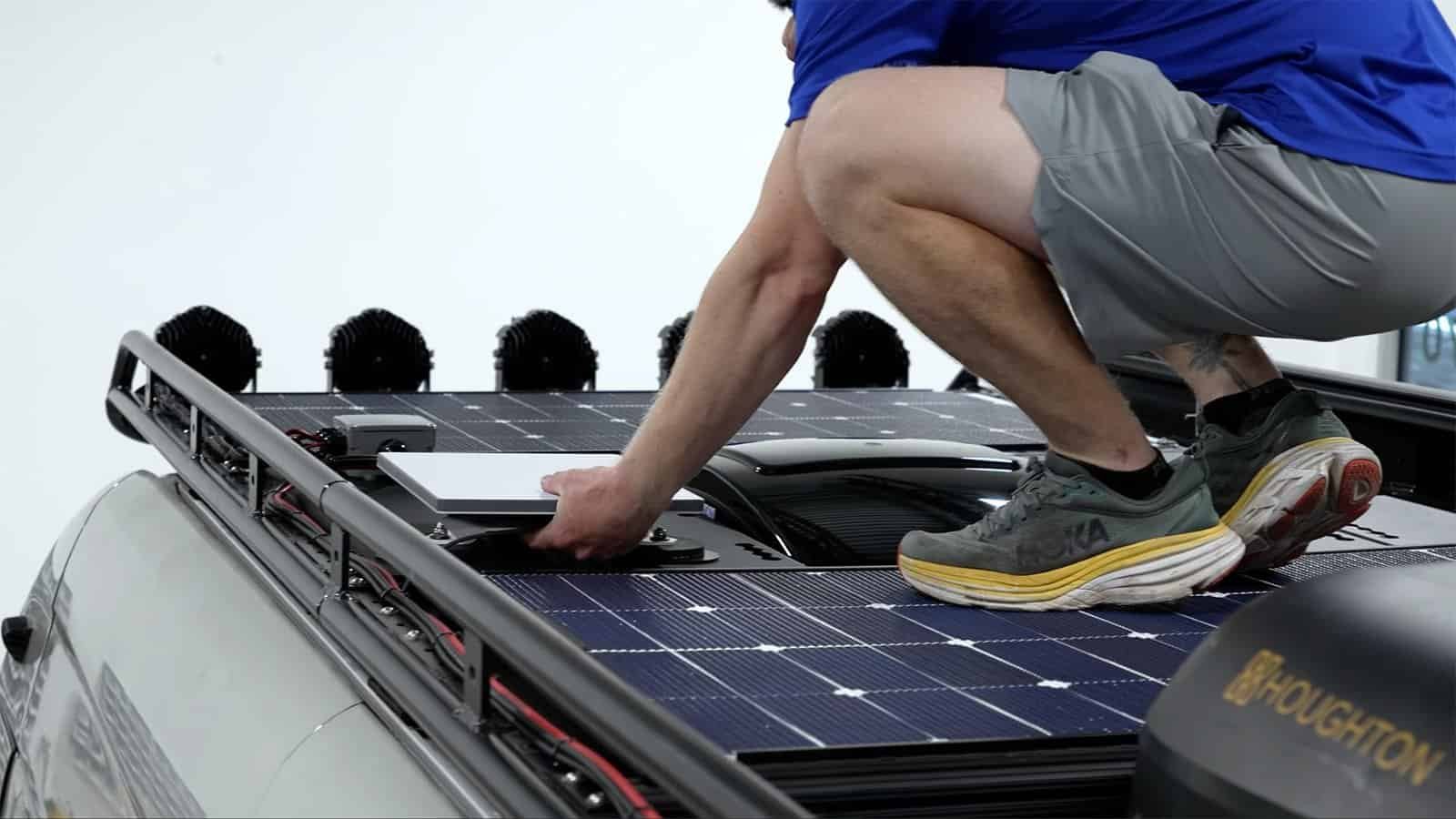
Standardpaneele sind für Dächer konzipiert. Ihre Anwendung betrifft wahrscheinlich kein Dach.
Diese Lücke ist der Grund für die Existenz von halbstarren Solarmodulen und dafür, dass so viele Marken individuelle Anfertigungen in Auftrag geben, anstatt aus einem Katalog zu kaufen. Im Folgenden werden die Probleme erläutert, mit denen Käufer tatsächlich konfrontiert werden, die technischen Lösungen dafür und wie ein OEM- oder ODM-Programm von der ersten E-Mail bis zur Serienproduktion abläuft.
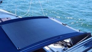
Kurzdefinition: Ein halbstarres Solarmodul ist ein glasfreies Panel, das auf einer stabilen Trägerplatte montiert ist und anstelle von gehärtetem Glas eine ETFE-Frontfolie verwendet. Es behält seine Form, ist für leichte Krümmungen geeignet und kann in begehbaren Ausführungen befahren werden. Aktuelle Produkte sind typischerweise 4–7 mm dick, im Vergleich zu etwa 30–35 mm bei einem gerahmten Glasmodul – unser eigenes starres Modul CLM-150MBC ist 30 mm dick.
Teil 1 – Das Problem
Katalog-Solarpaneele brechen das Produktdesign
Gewicht und Dicke behindern die Anwendung.
Ein gerahmtes Glasmodul ist schwer. Unser robustes Modell CLM-150MBC wiegt 7,5 kg und ist 30 mm hoch. Bei einer Bodenmontage ist das kein Problem. Auf einem Wohnwagendach, einem Bootsdeck oder einer mobilen Stromversorgungsanlage hingegen schon.
Jedes Kilogramm schlägt sich irgendwo nieder. Bei einem Fahrzeug verringert es die Nutzlast. Bei einem Boot erhöht es den Schwerpunkt. Bei einem versendeten Konsumprodukt schlägt es sich in der Frachtrechnung für jede verkaufte Einheit nieder.
Die Montagefläche ist selten eben.
Bootsdecks sind gewölbt. Lieferwagendächer sind gewölbt. Anhängerdeckel, Drohnenkörper und Telekommunikationsschränke haben alle eine bestimmte Form, und starres Glas passt sich keiner davon an. Daher überbrücken Monteure die Lücke mit Schienen, Halterungen und Abstandshaltern – Bauteile, die Höhe, Luftwiderstand und Kosten erhöhen und pro Befestigungselement eine neue Leckagequelle schaffen.
Niemand kann darauf laufen
Die Fläche von Terrasse und Dach ist begrenzt. Ein Solarpanel, das nicht betreten werden kann, stellt ein Hindernis dar. Der Eigentümer verliert dadurch gleich doppelt Platz: einmal durch das Panel selbst und einmal durch den darum herumführenden Gehweg.
Die Spannung passt nicht zum System
Die meisten im Handel erhältlichen PV-Module sind für den Betrieb in Netzsträngen ausgelegt, während netzunabhängige Produkte üblicherweise mit 12 V oder 24 V betrieben werden. Wählt man die falsche Spannung, verwirft der Laderegler entweder überschüssige Leistung oder erreicht an einem trüben Morgen nicht die erforderliche Ladeschwelle.
Das Solarpanel passt nicht – und es gehört Ihnen nicht.
Reale Produkte haben reale Abmessungen. Eine Luke ist 980 mm breit, ein Schrankdeckel 620 mm und das Katalogpanel 1134 mm; ein laminiertes Solarmodul lässt sich nicht nachträglich zuschneiden. Hinzu kommt das Etikett. Versendet man ein Solarmodul unter dem Namen eines anderen Unternehmens, baut man keine eigene Marke auf, sondern verkauft lediglich ein bestehendes Produkt weiter.
Teil 2 – Einblicke
Was ein gutes halbstarres Design tatsächlich ausmacht
Erkenntnis 1: “Halbstarr” beschreibt eine Struktur, nicht ein Material
Das verwirrt viele Käufer, denn flexible und halbstarre Solarmodule verwenden oft dieselbe Frontfolie und dasselbe Verkapselungsmaterial. Der Unterschied liegt auf der Unterseite und ist nicht sichtbar.
Ein flexibles Panel besitzt keine tragende Platte; es biegt sich frei und lehnt sich an die Oberfläche an, auf der es montiert ist. Ein halbstarres Solarpanel hingegen hat eine in das Laminat eingeklebte Trägerplatte, die die Last trägt und die Steifigkeit bestimmt.
Wenn ein Lieferant also von “halbstarr” spricht, klärt eine Frage den größten Teil der Angelegenheit: Aus welchem Material besteht die Trägerplatte und wie dick ist sie?
Erkenntnis 2: Die Trägerplatte fixiert fast alles
| Rückplatte | Steifheit | Gewicht | Hinweise |
|---|---|---|---|
| Aluminiumblech | Hoch | Höher | Verteilt die Last gut. Erfordert eine sorgfältige Auslegung der elektrischen Isolierung. |
| Glasfaserplatte | Mittel-hoch | Medium | Robust, formstabil, langjährige Erfolgsbilanz im Schiffbau. |
| Verbundkernplatte | Medium | Niedrig | Beste Steifigkeit pro Kilogramm im Mainstream-Segment. Häufig bei Schuhen für den Alltag zu verwenden. |
| Kohlenstofffaser | Sehr hoch | Sehr niedrig | In allen Kennzahlen hervorragend, außer bei den Kosten. Nur für Projekte geeignet, bei denen das Gewicht eine entscheidende Rolle spielt. |
Keine der Optionen ist eindeutig überlegen. Eine begehbare Solarterrasse und eine leichte Drohnenplattform ziehen entgegengesetzte Interessen an. Daher ist die Wahl der Solarplatte die erste wirkliche technische Entscheidung in jedem Projekt und diejenige, über die es sich am ehesten lohnt, frühzeitig zu diskutieren.
Erkenntnis 3: ETFE leistet mehr als nur Glas zu ersetzen
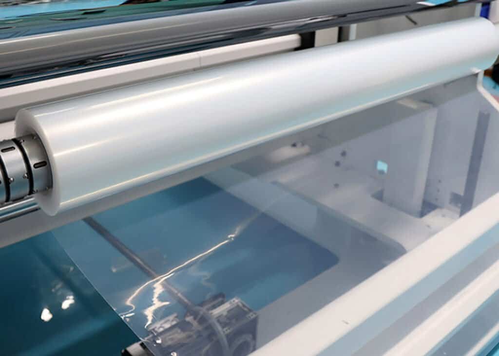
ETFE ist eine Fluorpolymerfolie, und die verlässlichen Daten stammen von den Harzherstellern und nicht aus Broschüren der Plattenhersteller. AGC produziert seine Fluon ETFE-Folie auf einem 12 µm bis 250 µm Reichweite und Berichte, dass ein Eine 50 µm dicke Schicht lässt etwa 95% des einfallenden Lichts durch.. Die Dicke von Solar-Frontfolien liegt üblicherweise im Bereich von einigen zehn Mikrometern bis zu einigen hundert Mikrometern, und die Wahl ist ein einfacher Kompromiss: Dickere Folien sind abriebfester, dünnere Folien lassen mehr Licht durch.
Die Langlebigkeit ist das überzeugendste Argument. AGC berichtet von nahezu keiner Beeinträchtigung nach 16.000 Stunden beschleunigter Bewitterung, was mehr als dreißig Jahren im Freien entspricht. Zudem wird ein Wasserkontaktwinkel von 106° angegeben. Dieser Wert erklärt, warum Schmutz und Salzablagerungen einfach abgespült werden, anstatt sich festzusetzen.
Fragen Sie Ihren Lieferanten danach.
Ein einziger Prozessschritt entscheidet darüber, ob überhaupt etwas davon im Inneren Ihres Solarmoduls erhalten bleibt. ETFE besitzt eine geringe Oberflächenenergie, daher muss die Folie vor der Laminierung einer Korona- oder Plasmabehandlung unterzogen werden. Wird dieser Schritt ausgelassen, versagt die Verbindung unbemerkt – die Delamination zeigt sich erst im dritten Jahr, nicht schon am ersten Tag, lange nachdem die Probe die Qualitätskontrolle bestanden hat.
Strukturiertes ETFE bietet noch einen weiteren, erwähnenswerten Vorteil: eine rutschfeste Oberfläche. Dank dieser Struktur ist eine begehbare Platte auch auf nassem Deck nutzbar und stellt keine Gefahr dar.
Erkenntnis 4: Rückkontaktzellen eignen sich ungewöhnlich gut für halbstarre Konstruktionen.
Bei rückseitig kontaktierten Zellen (BC-Zellen) befinden sich alle elektrischen Kontakte auf der Rückseite, wodurch die Vorderseite völlig frei bleibt. Ein kompaktes, glasfreies Modul, das Ihnen vier Vorteile bietet.
Schattenverhalten. Eine TÜV NORD-Studie berichtete darüber in PV Magazin stellte fest, dass Eine einzelne vollständig beschattete BC-Zelle benötigt etwa 12,91 TP3T Modulleistung, im Vergleich zu etwa 33,91 TP3T für ein vergleichbares TOPCon-Modul.. Der Mechanismus ist spezifisch. Eine BC-Zelle bricht bei etwa 5 V durch, aber es werden ungefähr 15 V Sperrspannung benötigt, bevor die Bypass-Diode aktiviert wird. Der Strom fließt also weiter, wo sich ein TOPCon-Teilstring bereits selbst abgeschaltet hätte.
Neben dieser Zahl gibt es zwei Einschränkungen, die selten erwähnt werden. Erstens wurde der Vorteil bei verteilter Verschattung innerhalb eines Strangs über verschiedene Teilstränge gemessen. Zweitens nimmt er schnell ab: BC liegt vorn, solange drei oder weniger Zellen verschattet sind. Sobald die Verschattung vier Zellen übersteigt, nähern sich die Verluste beider Technologien 501 TP3T an. Eine separate Studie von Trina Solar und der Universität Nanchang, veröffentlicht im August 2025, kam zu demselben Ergebnis. BC ist daher bei leichter, fleckenhafter Verschattung – etwa durch Schienen, Masten, Blätter oder Vogelkot – im Vorteil. Bei echter Verschattung ist der Vorteil jedoch dahin.
Die Gegenbeweise verdienen ebenfalls Beachtung. In TÜV Nord-verifizierten Feldtests in Kagoshima, Japan, Ein TOPCon-Modul erreichte ein Leistungsverhältnis von 94,191 TP3T gegenüber 91,991 TP3T für p-leitendes BC und 89,291 TP3T für n-leitendes BC.. Diese Tests wurden von TOPCon-Herstellern in Auftrag gegeben, daher sollte man dies bei der Interpretation berücksichtigen – die Kernaussage ist jedoch stichhaltig. Schattentoleranz ist nur eine von mehreren Variablen und nicht allein ausschlaggebend für den Ertrag. Bei kompakten netzunabhängigen Anlagen mit permanent nahen Hindernissen ist sie in der Regel die Variable, die das Ergebnis bestimmt. Auf einer freien, unbeschatteten Anlage hingegen beruht die Argumentation für BC auf ganz anderen Faktoren.
Wärmeverhalten. BC-Module tragen typischerweise ein Pmax Der Koeffizient liegt nahe bei −0,26%/°C. Die Größe dieses Gewinns sollte jedoch genau angegeben werden: LONGi beziffert die Verbesserung gegenüber TOPCon auf etwa 0,03%/°C., Das führt dazu, dass der TOPCon-Wert für gängige Anwendungen bei etwa −0,29%/°C liegt. Ein durchaus vorhandener Vorteil also, wenn auch ein bescheidener. Er macht sich vor allem dort bemerkbar, wo Zellen heiß laufen. Ein flach auf ein Trägermaterial geklebtes Panel ohne dahinterliegende Luftzirkulation wird tatsächlich sehr heiß. Das ist aber auch die Kehrseite der Medaille: Dieselbe Montageart reduziert einen Teil der Vorteile, die die Zelltechnologie gerade erst gebracht hat.
Mechanische Belastung. Eine schienenlose Vorderseite weist weniger Spannungskonzentrationen auf, was bei einem Panel, das sich leicht biegen und betreten werden soll, von Bedeutung ist.
Aussehen. Keine Rasterlinien, keine sichtbaren Verbindungen. Auf einem Yachtdeck oder einer architektonischen Oberfläche wirkt einheitliches Schwarz einfach perfekt.
Erkenntnis 5: Die Abdeckung bestimmt nicht die Leistung – die Zellen tun es.
Hier ist ein Vergleich, der viele überrascht. Nehmen wir unseren starren CLM-150MBC und bauen Sie die identische 3 × 12-Rückkontaktanordnung als halbstarres ETFE-Laminat nach. Gleiche Zellen, gleiche Reihenzahl, gleiche Grundfläche. Die elektrischen Spezifikationen bleiben gleich, da das Glas die Energie ursprünglich nie erzeugt hat.
Optisch stimmt das. AR-beschichtetes Solarglas und eine dünne ETFE-Frontfolie weisen eine nahezu identische Lichtdurchlässigkeit auf, sodass ein identisches Zellarray die gleiche Wattzahl liefert. Was sich ändert, ist die gesamte Struktur – und genau das ist der Kern der Sache.
| Parameter | CLM-150MBC (starres Glas) | CLM-150ME (Beispiel für eine halbstarre Konstruktion) |
|---|---|---|
| Maximale Leistung (Pmax) | 150 W | 150 W |
| Leistungstoleranz | 0 bis +3% | 0 bis +3% |
| Maximale Leistungsspannung (Vmp) | 22,86 V | 22,86 V |
| Maximale Leistungsstromstärke (Imp) | 6,57 A | 6,57 A |
| Leerlaufspannung (Voc) | 26,1 V | 26,1 V |
| Kurzschlussstrom (Isc) | 6,97 A | 6,97 A |
| Zelltyp | Rückkontakt Mono (HPBC std) | Rückkontakt Mono (HPBC std) |
| Zellarray | 3 × 12 | 3 × 12 |
| Koeff. Pmax | −0,26%/°C | −0,26%/°C |
| Koeff. Voc / ICHsc | −0,22%/°C / +0,05%/°C | −0,22%/°C / +0,05%/°C |
| Betriebstemperatur | −40 bis +85 °C | −40 bis +85 °C |
| Bypass-Dioden | 2 | 1 oder 3, je nach Layout |
| Vorderseite / Struktur | Gehärtetes Glas + Aluminiumrahmen | ETFE + PoE + Trägerplatte |
| Dicke | 30 mm | ca. 5 mm |
| Gewicht | 7,5 kg | Etwa die Hälfte, abhängig vom Teller |
Liest man die Tabelle, ergibt sich die Argumentation von selbst. Jede elektrische Leitungsreihe ist identisch. Übrig bleiben 25 mm Dicke und einige Kilogramm. Auf einem Boot oder in einem Lieferwagen war das schon immer der einzige Unterschied, der zählte.
Der ehrliche Vorbehalt
Gleiche STC-Werte garantieren keine gleiche Ernte. Der STC-Wert wird bei einer Zelltemperatur von 25 °C gemessen. Ein halbstarres, auf eine Unterkonstruktion geklebtes Modul verliert die rückseitige Konvektion, die ein gerahmtes, luftspaltbegrenztes Glasmodul bietet. Es wird im Betrieb heißer, sodass der Jahresertrag selbst bei identischer Nennleistung hinter dem eines Glasmoduls zurückbleiben kann. Planen Sie, wo immer möglich, einen Luftspalt oder einen Abstandshalter ein – und falls dies nicht möglich ist, dimensionieren Sie die Anlage entsprechend.
Warum die Diodenanzahl ein Bereich und keine Zahl ist
Beachten Sie, dass im Beispiel mit der halbstarren Schaltung ein bis drei Bypass-Dioden anstelle einer festen Anzahl aufgeführt sind. Dies ist beabsichtigt, da die Anzahl der Dioden bei einem kleinen Modul eine Designentscheidung mit realen Auswirkungen darstellt.
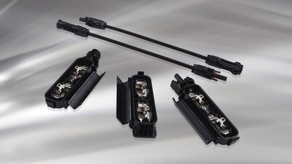
Eine einzelne Diode ist am günstigsten und benötigt in einer flachen Anschlussdose am wenigsten Platz. Sie schützt das Solarmodul als Einheit, sodass bei Verschattung das gesamte Modul ausfällt. Zwei Dioden teilen einen 36-Zellen-String in zwei Hälften. Drei Dioden teilen ihn in Drittel: Eine verschattete Ecke reduziert die Leistung dann auf ein Drittel anstatt auf die gesamte, allerdings auf Kosten einer größeren Anschlussdose und zusätzlicher Verbindungen.
Hierbei gibt es eine Besonderheit bei BC-Zellen zu beachten. Da BC-Zellen einen sanften Abbauprozess aufweisen, tolerieren sie leichte interne Verschattung, bevor die Diode überhaupt zum Einsatz kommt. Dies verändert die sinnvolle Lage der Dioden. Bei begehbaren Modulen ist dies ohnehin oft durch die physikalischen Gegebenheiten bedingt: Ein dünnes Laminat bietet nur begrenzten Platz für die Anschlussdose, und flache Dosen fassen weniger Dioden. Teilen Sie uns daher bitte das erwartete Verschattungsmuster mit, und die Anzahl der Dioden richtet sich danach und nicht nach einem Standardwert aus dem Katalog.
Spannung ist eine Konstruktionsentscheidung, keine feste Eigenschaft.
Die Anzahl der in Reihe geschalteten Zellen bestimmt die Spannung; Zellgröße und -anordnung bestimmen den Strom. Ändert sich einer dieser Parameter, ändert sich auch die Systemkompatibilität des Solarmoduls. Die Spannung ist der am meisten unterschätzte Stellhebel bei der Entwicklung kundenspezifischer Module und wird oft zu spät festgelegt.
Der häufigste kostspielige Fehler
AVmp von 22,86 V ist nicht Ein “12-V-Nominal”-Panel, obwohl das Modul für 12-V-Systeme ausgelegt ist. Ein PWM-Controller fungiert im Prinzip als Schalter. Er senkt die Spannung des Solarpanels auf Batteriespannung – bei einer 12-V-Batteriebank etwa 14 V. Technische Anmerkung von Victron Der Mechanismus wird anschaulich erklärt. Kombiniert man diese Schaltung mit PWM an einer 12-V-Batterie, gehen etwa 35–401 TP3T der verfügbaren Leistung verloren. Das Panel erreicht schlichtweg nie seinen maximalen Leistungspunkt.
Die CLM-150ME-Zeichenkette möchte also MPPT, Dadurch wird die Überspannung in zusätzlichen Ladestrom umgewandelt. Betrachten Sie dies als Vorteil, nicht als Einschränkung. Eine höhere Array-Spannung bedeutet außerdem dünnere Kabel und einen geringeren Spannungsabfall über längere Strecken – genau das, was ein Boots- oder Busdach benötigt.
Soll das Produkt mit einem kostengünstigen PWM-Controller funktionieren, geben Sie dies bitte in der Beschreibung an. Wir bauen dann einen echten 12-V-String mit V.mp Im 17–18-V-Bereich – gleiches Solarmodulformat, unterschiedliche Reihenanzahl. Genau deshalb gehört die Spannungsangabe in die erste E-Mail und nicht in die letzte.
Die hier dargestellte Konfiguration des CLM-150ME basiert auf dem Zellarray CLM-150MBC und dient als Beispiel. Die endgültigen Werte werden in der zum Zeitpunkt der Bestellung freigegebenen Zeichnung bestätigt.
Erkenntnis 6: OEM und ODM sind nicht dasselbe.
| OEM | ODM | |
|---|---|---|
| Wem gehört das Design? | Du tust | Die Fabrik passt es an oder stellt es her. |
| Was Sie liefern | Zeichnungen, Spezifikationen, Ziele | Eine Anwendung und ein Problem |
| Am besten, wenn | Die Spezifikationen kennen Sie bereits. | Sie benötigen technische Unterstützung |
| Typische Bleiarbeiten | Werkzeuge und Validierung | Layoutstudie, dann Werkzeugbau |
| Probenphase | Zum Drucken erstellen | Konzept, dann Druckversion |
In der Praxis bewegen sich die meisten Projekte irgendwo zwischen diesen beiden Säulen. Ein Käufer kommt mit einer groben Skizze und den Angaben zur Batteriespannung, und die Fabrik übernimmt die Layoutplanung. Das funktioniert einwandfrei, vorausgesetzt, allen Beteiligten ist klar, wer wofür die Genehmigung erteilt.
Erkenntnis 7: Testdaten überwinden eine Zertifikatsbarriere
Kundenspezifische Varianten werden in der Regel so gefertigt, dass sie die IEC-Normen erfüllen oder übertreffen, anstatt einzeln zertifiziert zu werden, da jede Variante ein eigenständiges Design darstellt. Es ist wichtig, die Bedeutung dieser Aussage genau zu definieren. “Gefertigt nach IEC 61215” ist eine Herstellerangabe; ein Zertifikat ist ein Prüfbericht einer unabhängigen Prüfstelle, der sich auf eine bestimmte Stückliste bezieht. Sie sind nicht austauschbar.
Welches Modul Sie benötigen, hängt vom Zielmarkt ab, nicht vom Modul selbst. Ein auf einem Bootsdeck oder Fahrzeugdach befestigtes Modul gilt als mobile Ausrüstung und fällt nicht unter die Bauvorschriften. Wird ein Modul in den USA an einem Gebäude montiert, benötigt es in der Regel eine NRTL-Zertifizierung nach UL 61730, bevor es von einem Prüfer abgenommen wird. UL Solutions erläutert, wie NEC, IBC und IRC diese Anforderung steuern.. In der EU gelten CE-Kennzeichnungspflichten. Klären Sie dies unbedingt bereits in der Planungsphase, denn die nachträgliche Zertifizierung eines bereits fertiggestellten Designs ist der teuerste Fehler in diesem Bereich.
Zu den technischen Bezugspunkten, IEC 61215-2:2021 Dieses Dokument ist maßgeblich. Die zweite Auflage enthielt einen Biegetest (MQT 22) speziell für flexible Module. Zyklische mechanische Belastung (MQT 20) und PID-Erkennung (MQT 21) wurden ebenfalls in dieser Überarbeitung eingeführt. Statische Belastung (MQT 16), Feuchtwärme, Temperaturwechsel und Frost-Feuchte-Tests decken den Bereich Feuchtigkeit und Materialermüdung ab. Diese Auflage überarbeitete auch den thermischen Test der Bypass-Dioden (MQT 18), der relevant ist, wenn Ihre Schaltung mehr als eine Diode enthält.
Eine ehrliche Einschränkung
Es gibt keine PV-Modulnorm, die den Begriff “begehbar” definiert.” IEC 61215 enthält keinen Test zur Fußgängerbelastung, IEC 63092-1 Der nächstliegende Rahmen betrachtet BIPV-Module als Bauprodukte und nicht als begehbare Terrassenbeläge. Jede Angabe zur Begehbarkeit in diesem Markt basiert daher auf den jeweiligen Herstellervorgaben. Fragen Sie nach den Testbedingungen: Belastung, Kontaktfläche, Unterkonstruktion und Anzahl der Ladezyklen. Eine Zahl ohne Angabe der Testbedingungen ist völlig wertlos.
Teil 3 – Lösungen
Wie ein kundenspezifisches halbstarres Programm abläuft
Schritt 1 – Die Kurzbeschreibung
Fünf Dinge bringen uns in Bewegung: die Anwendung und ihre Montageart, der verfügbare Platz einschließlich etwaiger Krümmungen, die Systemspannung und der Controllertyp, Ihre angestrebte Wattzahl und der Zielmarkt.
Eine grobe Skizze genügt. Ehrlich gesagt sagt uns ein Foto der Montagefläche oft mehr als eine CAD-Datei.
Schritt 2 – Überprüfung von Layout und Design
Die Konstruktion geht vom verfügbaren Platz aus. Zellgröße, Zellanzahl, Stranganordnung, Diodenplatzierung, Trägerplatte und Laminatstapel werden in dieser Phase festgelegt.
Bevor mit dem Bau begonnen wird, sollten Sie eine bemaßte Zeichnung und eine voraussichtliche elektrische Spezifikation zur Hand haben.
Schritt 3 – Beispielaufbau
Ein oder zwei Einheiten gemäß der genehmigten Zeichnung. Zuerst die Passform, dann die elektrische Leistung und schließlich die Endbearbeitung prüfen – in dieser Reihenfolge, denn ein nicht passendes Panel macht die anderen beiden Prüfungen irrelevant.
Schritt 4 – Validierung
Testen Sie die Probe so, wie das Produkt später tatsächlich eingesetzt wird: Montieren, belasten, im Freien lagern. Fügen Sie Salzwasser für den Einsatz auf See und Vibrationen für Fahrzeuge hinzu. Dieser Schritt deckt Probleme auf, die kein Datenblatt jemals aufzeigen wird.
Schritt 5 – Pilotlauf und Produktion
Mit einem Pilotprojekt mit niedriger Mindestbestellmenge können Sie den Markt testen, bevor Sie größere Mengen bestellen. Das Feedback aus der ersten Charge verbessert fast immer die zweite.
Was Sie anpassen können
- Abmessungen, Form und Eckradius
- Leistung, Vmp, Voc, und Zellenlayout für 12 V, 24 V oder höher
- Material und Dicke der Trägerplatte
- Bypass-Diodenanzahl und Teilstringgrenzen
- Vorderseite: klar, strukturiert oder rutschfest
- Farbe der Rückseitenfolie, einschließlich vollständig Schwarz
- Kabellänge, Querschnitt, Austrittsposition und Steckertyp
- Anschlusskasten-Bauform, einschließlich flacher und seitlicher Ausführung
- Montageart: Ösen, klebstoffgeeignete Oberfläche, verklebte Bolzen oder Kantenanleimung
- Zelltechnologie: HPBC-Standard, mit ABC- oder TBC-Optionen
- Eigenmarken, aufgedrucktes Logo, Seriennummerierung und individuelle Verpackung
Checkliste für Spezifikationen vor der Unterzeichnung
- Aus welchem Material besteht die Trägerplatte und welche Dicke hat sie?
- Wie sieht der vollständige Laminataufbau von vorne nach hinten aus?
- Wird das ETFE vor der Laminierung oberflächenbehandelt?
- Welches Verkapselungsmaterial – EVA, POE oder EPE – und warum?
- Wie hoch ist die Gesamtdicke und das Gewicht pro Einheit?
- Was sind V?mp und Voc bei der angestrebten Betriebstemperatur, nicht nur bei STC?
- Für welchen Regler ist diese Zeichenkette ausgelegt – MPPT oder PWM?
- Ist der kälteste Tag Voc Unterhalb der Eingangsgrenze des Controllers bleiben?
- Wie viele Bypass-Dioden werden benötigt und wo liegen die Substringgrenzen?
- Wie wird das Panel gekühlt, und welche Leistungsreduzierung gilt, wenn es flach verklebt wird?
- Falls die Begehbarkeit behauptet wird, unter welcher Belastung, welchen Auflagerbedingungen und welcher Anzahl von Zyklen?
- Ist für den Zielmarkt ein Zertifikat eines Drittanbieters erforderlich, und wer besorgt es?
- Was deckt die Garantie ab und wie werden Garantieansprüche bearbeitet?
Häufig gestellte Fragen
Worin besteht der Unterschied zwischen flexiblen und halbstarren Solarmodulen?
Flexible Paneele sind biegsam und benötigen zur Stabilisierung die Montagefläche. Halbstarre Paneele verfügen über eine tragende Trägerplatte im Inneren des Laminats, wodurch sie ihre Form behalten und die Last gleichmäßig verteilen.
Erzeugt eine halbstarre Scheibe weniger Leistung als eine Glasscheibe?
Nicht unter Standardtestbedingungen (STC). Die Zellen erzeugen den Strom, und ETFE lässt Licht ähnlich gut durch wie AR-beschichtetes Glas. Ein identisches Zellenfeld hat daher die gleiche Nennleistung, und das Beispiel CLM-150ME entspricht dem CLM-150MBC Watt für Watt. Im Betrieb sieht es etwas anders aus: Flach verklebt und ohne Luftzirkulation dahinter, wird das Panel heißer und kann über ein Jahr etwas weniger Strom liefern. Berücksichtigen Sie dies bei der Dimensionierung des Zellenfelds.
Kann man auf einem halbstarren Solarpanel tatsächlich laufen?
Begehbare Ausführungen sind möglich, sofern sie vollständig abgestützt sind und über die geeignete Unterkonstruktion und Oberfläche verfügen. Eine nicht abgestützte Spannweite stellt einen völlig anderen Lastfall dar. Da keine PV-Norm einen Test für Fußgängerverkehr vorschreibt, sollten Sie die Testbedingungen des Herstellers erfragen, anstatt sich auf die angegebenen Werte zu verlassen.
Wie viele Bypass-Dioden sollte mein Modul haben?
Bei einem Modul dieser Größe sind ein bis drei Dioden erforderlich. Die optimale Anzahl hängt vom Verschattungsmuster und dem verfügbaren Platz in der Anschlussdose ab. Eine einzelne Diode ist die günstigste und flachste Lösung, legt aber das gesamte Panel lahm, sobald sie auslöst. Drei Dioden ermöglichen eine präzisere Wiederherstellung, benötigen jedoch eine größere Anschlussdose. Beschreiben Sie die Schattenwurfpositionen in Ihrer Anwendung; die Anzahl der benötigten Dioden ergibt sich daraus.
Benötige ich MPPT oder PWM?
Das hängt von der Saite ab, die wir bauen. Eine hohe V-Saitemp Eine Stringschaltung wie die CLM-150ME benötigt MPPT, da PWM die Spannung auf die Batteriespannung begrenzen und einen Großteil der Ausgangsleistung ungenutzt lassen würde. Wenn PWM zwingend erforderlich ist, wird stattdessen eine Stringschaltung mit echter 12-V-Nennspannung ausgelegt.
Sind Ihre kundenspezifischen Module zertifiziert?
Kundenspezifische Varianten werden gemäß den Normen IEC 61215 und IEC 61730 gefertigt. Ob ein Zertifikat von Drittanbietern erforderlich ist, hängt vom Zielmarkt und der Montageart ab, da mobile und netzunabhängige Geräte anders behandelt werden als fest installierte Systeme. Teilen Sie uns Ihren Zielmarkt frühzeitig mit, und wir erarbeiten die passende Lösung.
Unterstützen Sie Testläufe mit geringer Teilnehmerzahl, und können wir diese mit unserem Branding versehen?
Ja, beides trifft zu. Mit Pilotprojekten mit niedrigen Mindestbestellmengen können Sie ein Design zunächst am Markt validieren. Eigenmarken, bedruckte Logos, individuelle Seriennummernformate und Markenverpackungen sind ab der Pilotphase verfügbar.
Sprechen Sie mit Couleenergy über Ihr Semi-Rigid-Projekt.
Couleenergy (Ningbo Coulee Tech Co., Ltd.) fertigt flexible, halbstarre und starre Module mit rückseitigem Kontakt für OEM- und ODM-Kunden in Nordamerika und Europa. Kundenspezifische Größen, Leistungen, Formen, Spannungen, Oberflächen und Branding sind Standard; Testbestellungen mit geringen Mindestbestellmengen sind möglich.
Senden Sie uns Ihre Bewerbung, die verfügbare Fläche, die Systemspannung und den Regler-Typ. Wir senden Ihnen anschließend einen Layoutvorschlag und eine voraussichtliche Spezifikation.
E-Mail: info@couleenergy.com
Tel.: +1 737 702 0119
Web: couleenergy.com
OEM & ODM · Niedrige Mindestbestellmenge · Kundenspezifische Größe, Leistung & Form · Schnelle Mustererstellung
Verweise
- Eine Studie von TÜV NORD zeigt, dass der Vorteil von Rückkontakt gegenüber TOPCon auf leichte Verschattungsbedingungen beschränkt ist. — pv magazine, 8. Juli 2026. Quelle der Einzelzellenwerte 12,9% / 33,9%, der Vierzellenschwelle und des 5-V-Durchbruch-/15-V-Diodenaktivierungsmechanismus. Berichtet über die Studie “Eine vergleichende Untersuchung der Leistung von BC- und TOPCon-Modulen unter Teilschattierungsbedingungen”, veröffentlicht in Sonnenenergie, und die Studie von Trina Solar / der Universität Nanchang vom August 2025, die einen vergleichbaren Schwellenwert erreicht.
- JinkoSolar und Trina geben an, dass TOPCon-Module P-Typ-Rückkontakt-Panels übertreffen. — pv magazine, 18. Oktober 2024. Unabhängiger Bericht über die vom TÜV Nord verifizierten Feldtests in Kagoshima und die Leistungsverhältnisse 94,19% / 91,99% / 89,29%.
- Einführung von LONGi Hi-MO X10 / HPBC 2.0 — LONGi. Quelle des Koeffizienten −0,26%/°C und des Deltas ~0,03%/°C gegenüber TOPCon.
- IEC 61215-2:2021 — Terrestrische PV-Module: Designqualifizierung und Typgenehmigung, Teil 2: Prüfverfahren (IEC Webstore). Die zweite Auflage ergänzt die Biegeprüfung MQT 20, MQT 21 und MQT 22 für flexible Module und überarbeitet die thermische Prüfung der Bypassdiode MQT 18.
- IEC 63092-1:2020 — Photovoltaik in Gebäuden, Teil 1: Anforderungen an BIPV-Module.
- Prüfung und Zertifizierung von BIPV-Systemen — UL Solutions, auf NRTL-Listung und UL 61730 gemäß NEC, IBC und IRC.
- Fluon ETFE-Film Und Funktionen und Vorteile — AGC Chemicals. Filmdickenbereich, 95%-Transmissionsgrad bei 50 µm, Bewitterungsergebnis nach 16.000 Stunden, Kontaktwinkel 106°.
- Welcher Solarladeregler: PWM oder MPPT? — Technischer Hinweis von Victron Energy. Erklärt, warum ein PWM-Regler die Array-Spannung auf die Batteriespannung herunterzieht.
- Halbstarre Solarpaneele für Boote, Transporter und Dockdecks — Couleenergie.
- HPBC oder ABC? Vergleichen Sie die Back-Contact-Solarmodultechnologien — Couleenergie.
- BC Solarmodule, flexible Paneele und kundenspezifische OEM-Lösungen aus China — Couleenergie.
- Solarmodule im Schatten: HPBC 2.0, ABC vs. TOPCon im Vergleich — Couleenergie.
Alle oben genannten Quellen wurden auf ihre Verfügbarkeit im August 2026 geprüft. Normen und Produktdaten ändern sich; bitte bestätigen Sie die aktuellen Versionen vor dem endgültigen Designabschluss.



 Deutsch
  English
  Español
  Français
  Русский
  العربية